

By Greg Hjelstrom with Modifications from the W3DHub team
Introduction
W3D uses a form of rigid body dynamics to simulate a wide variety of vehicles. All of the geometric characteristics of a vehicle are determined directly from a model which is exported from 3ds-max. For example, the number, placement, and behavior of any wheels in the vehicle is determined by the set of “bones” in the model. Many wheel configurations can be defined by the model: front-wheel drive, four-wheel steering, all-wheel drive, tank tracks, etc can all be set up. Parameters such as the mass, engine strength, and suspension stiffness are set in Mammoth, the W3D level editor.
Vehicle Balance/Origin Bone
The first thing to do is to position your vehicle model such that its center of mass is at the origin in 3ds Max, this is usually marked by an Origin bone. In the X-Y plane, the CM (center of mass) should usually be placed exactly at the centroid of all of the wheels in the vehicle. If the CM behind this point, the vehicle will lean backwards on its suspension, if it is in front of this point, it will lean forward, etc. In the Z axis, the CM should be placed some distance below the center of the object to help prevent tipping over when turning corners.
Collision Detection (WorldBox)
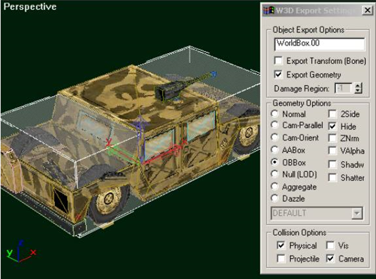
As is the case with all objects in W3D, you can use separate meshes for projectile collision detection and physical collision detection. In the case of vehicles you have to use a single OBBox named "WorldBox" for physical collision detection. (Note: physical collision detection is used when the object is moving in the world, projectile collision detection is used when the code is determining whether bullets hit the vehicle). For projectile collision detection, just use some representative meshes from your model. The WorldBox OBBox must be linked to the origin of the vehicle, and be aligned with the world axes. It should also be as small as possible while still containing the wheels and bulk of the body of the vehicle. The physics code in W3D collides with objects in a buffer zone near the surface of the worldbox so it should not completely contain the model. Below is a screenshot of a WorldBox. Note how the WorldBox does not extend all the way to the front, top or back of the vehicle.
WorldBox checklist
- It should be named exactly "WorldBox" (or "WorldBox.00" when part of an LOD model)
- It should only exist in the top LOD of your vehicle
- It should be set up to export as an OBBox
- It should be Hidden
- It should have its Physical and Camera collision settings enabled
- It should be the only object in the vehicle model with Physical and Camera collision enabled
- It should be as small as possible while still containing the wheel contact patches in their initial position (more on this later).
Wheels
Wheels are defined by adding bones with a particular naming convention into your model. All vehicles, including VTOL aircraft, have wheels. At the bare minimum, there must be two bones per wheel; one to define the contact point of the wheel and one to define the center of rotation of the wheel. The code will use the pivot points of the wheel bones to determine the following things: the initial position of the wheel, the radius of the wheel, the axis that the suspension travels along, and the axis that the wheel rotates about. The two basic bones needed by each wheel are the "WheelP" (wheel position) bone, and the "WheelC" (center) bone.
Below is a view of a wheel from the Humm-Vee model (with the WheelP bone selected). Note that the z-axis points along the direction of travel of the suspension and the x-axis points forward. Also, the pivot point of the WheelP bone must be contained inside the world-box. The initial position of all wheels should be at their extreme topmost point; imagine that the vehicle has just fallen off a skyscraper and landed directly on its wheels.

Attached to the wheel position bone, you need a bone which defines the center of rotation of the wheel; the WheelC bone. Below is a view of a wheel with both bones set up. Again, the important axis is the z-axis, it points along the axis of rotation of the wheel; in the "Top" viewport in Max, the z-axis should be pointing down your monitor (for all four wheels).
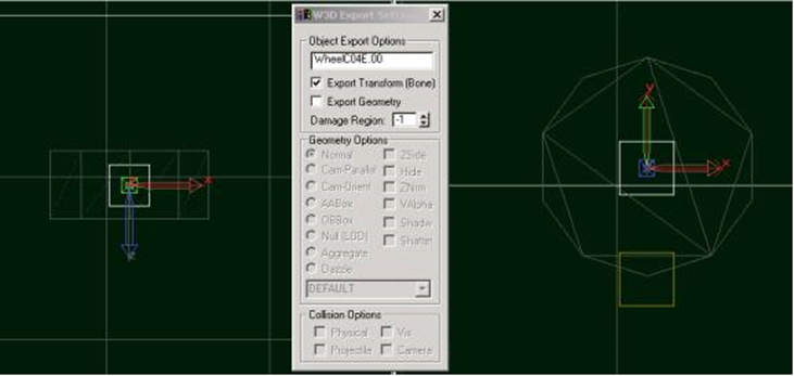
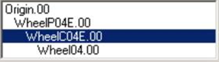
The graphical representation of the wheel is then attached to the WheelC bone and will rotate and translate as the vehicle is simulated. The simulation pays no attention to the graphical representation of the wheel or even whether it exists or not. The hierarchical linkage for a simple wheel should look like the one below. Note that the WheelC bone is attached to the WheelP bone; not the other way around.
The 'E' at the end of each of the names above is a flag signifies that this particular wheel applies the engine force at its contact point. Through this naming convention you can create four-wheel drive, front-wheel drive, or rear-wheel drive wheels. Other flags that are available include:
- S - The wheel will turn when the vehicle changes its steering parameter.
- I - The wheel will turn in the opposite direction of the vehicle's steering parameter (rear wheel steering).
- T - Intended for tilt steering. Currently a clone of the "S" flag
- E - The wheel will exert the engine force at its contact point
- L - The wheel is part of the left track of a tracked vehicle
- R - The wheel is part of the right track of a tracked vehicle
- F - The wheel is "fake"; it will graphically move with the vehicle but no forces are computed.
- H - The wheel is a "Hover" wheel; it will ignore any surface friction and drag, and use the default values.
The complete naming convention for a wheel bone is below. The name always starts with the word 'Wheel', followed by a single character and a two digit number (e.g. WheelP00). Following the digits, any of the above flags can be added.
Wheel {P,C,T,F} {00} [S] [I] [E] [L] [R] [F] [H]
Here are some examples of valid wheel bone names:
- WheelP00ES - The contact point of wheel 00 which has the engine force and steering applied to it
- WheelC05 - The rotation axis of wheel 05 which only exerts a suspension force and rolls with the vehicle
Advanced Wheel Settings
You may notice that there are two more types of wheel bones that have not been described yet. These bones can be used to create wheels whose suspension moves in a manner more complex than simply translating along the z-axis of the WheelP bone. First I'll show an example of a translational constraint using a WheelT bone. This example is from the front wheel of the Nod Recon Bike:
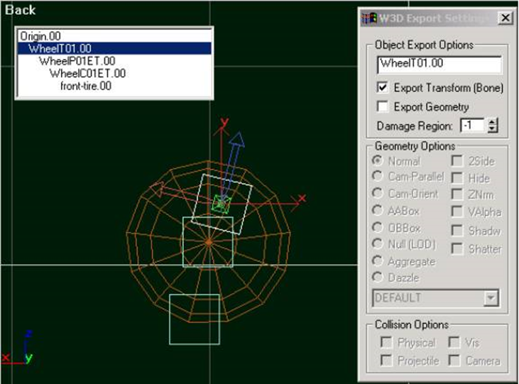
The presence of the WheelT bone in a wheel hierarchy causes the wheel to translate along the Z-axis of the WheelT bone rather than the contact point bone. This is used for the front tire of the Nod Recon Bike.
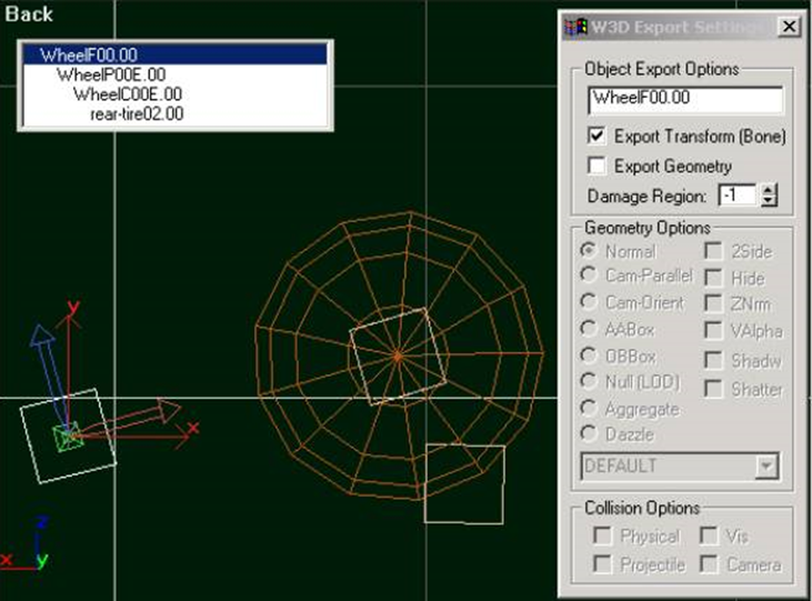
The rear wheel of a Recon Bike rotates along an arm. This can be accomplished by using a WheelF bone. Below is a picture of that situation. The WheelF bone will be rotated about its Y-axis to maintain contact between the wheel and the ground (see the picture for how to set it up). This is probably the most complex type of wheel to create... Look at the Nod Recon Bike for reference.
Wheel Checklist
- Each wheel should have a bone named WheelPxx and WheelCxx (where xx is a two digit number)
- All wheel bones should have all W3D options disabled except for Export Transform
- The wheels should be positioned at their extreme topmost position (smashed into the vehicle) and their contact points must be contained inside the world box of the vehicle.
- The hierarchy should look like this: Origin->WheelP->WheelC->Graphical Wheel
- The Z axis of all WheelP bones should point along the direction of travel of the suspension
- The X axis of all WheelP bones should point towards the front of the vehicle (direction of rolling)
- The Z axis of all WheelC bones should point along the axis of rotation of the wheel (typically down in the Top viewport)
- All wheel bones should have their flags set (append an 'E' to the wheels that are attached to the engine, append an 'S' to the wheels that steer, etc)
Turrets
Vehicles can have turrets which can fire weapons. The turret aiming motion is generated by the game code as long as certain bones are present in the model. There are three types of bones involved in controlling a turret. The 'Turret' bone will be rotated to set the turret's 'heading'. The 'Barrel' bone will be rotated to set the tilt of the weapon. And the 'Muzzle' bone will be used as the location to create projectiles from. Below is a picture of a the turret from the GDI Mammoth Tank:
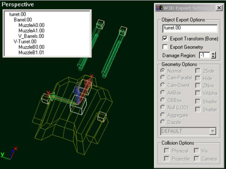
In the above picture, you can see that there are several muzzle bones. All of the bones follow the convention that their axes should be aligned with the world axes; Z is up, X points towards the front of the vehicle, Y points to the left of the vehicle. If you create your boxes in the 'Top' viewport, they will be oriented in this fashion automatically. One improvement over the linkage shown above would be to attach the V_Barrels mesh as a child of their Muzzle bones because the game engine automatically applies a recoil to the muzzle bone (attaching them in that way would cause the meshes to recoil when the weapon is fired).
Vehicles with more than a single Barrel bone
If you have a vehicle with two muzzle bones aligned side by-side and offset from the center, you can make the barrels yaw inwards to meet the target. Using the same naming convention that is used for the Muzzle bones (MuzzleA, MuzzleB etc.) you can setup barrels that behave in this way. For example, a vehicle that is setup with a BarrelA0 and a BarrelA1 bone will automatically yaw it's barrels inwards to make hitting targets a lot easier. Below is a picture of how this can be achieved, using a test model.
(Image of BarrelA0 and BarrelA1 bones in use)
Vehicles with Gatling barrels
Vehicles can support barrels that spin, in cooperation with the gatling tech in the weapon definition. To have models with these spinning parts, name the part of the weapon that you wish to spin spin_barrel_x (where x is either 0 or 1, as you can only have two.) and adjust the pivot so that the x-axis points in the direction you want the part to spin (this is normally parallel to the barrel. See the below image for an example. The blue gatling barrels are named spin_barrel_0 and have their pivot with the x axis pointing down the barrels.)
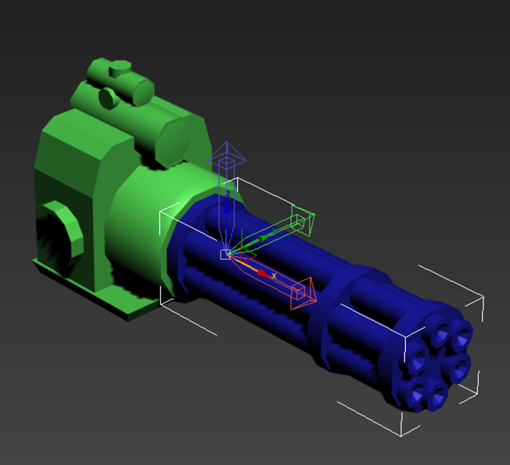
Make sure that you still have a Barrel bone, as this does not replace that. Furthermore, make sure that the weapon in use is set up as a gatling weapon!
Turret Checklist
-
The model should contain a 'Turret' bone, either a 'Barrel' bone or a BarrelA0 and BarrelA1 bone, as well as one or more muzzle bones.
- There can be up to 26 Muzzle bone 'sets'. e.g. MuzzleA, MuzzleB, MuzzleC, all the way to MuzzleZ.
- There can be any number of Muzzle bones per Muzzle bone sets. The number of muzzles per set does not have to be equal. e.g. You could have 2 MuzzleA bones, 4 MuzzleB bones and 1 MuzzleC bone, if you so desire.
- The bones should be connected in the hierarchy shown above.
- Visible meshes in the model should attach to the appropriate bones so that they move when the game logic controls the turret (i.e. the turret mesh should be attached to the turret bone so that it will rotate properly)
- All of the bones should have their pivot points aligned with the world axes.
- All bones should have Export Transform enabled and Export Geometry disabled.
Engine Special Effects
VTOL vehicles can control bones to display engine effects. Here are some examples of engine effects:
- The flame on the Orca engine lengthens when the vehicle accelerates or climbs (EngineFlame)
- The Orca engine rotates forward and back as the vehicle accelerates or decelerates (EngineAngle)
- The rotors on helicopters spin when they are in flight (Rotor/RotorA/RotorB)
Any bone present in the model which starts with the name "EngineFlame" will translate along its Z-axis along with the vehicle's acceleration. Any bone present which starts with the name "EngineAngle" will rotate about its Z-axis. In the screenshot below, the EngineAngle bone for one of the Orca engines is selected. Below it is the EngineFlame bone and not shown is a skin which has vertices attached to both bones and stretches as the EngineFlame translates.

Helicopter vehicles can use the EngineAngle bone to tilt their rotors as they fly forwards and backwards. In addition, they can contain 'Rotor' bones which will spin about their Z-axis when in flight. The parameters for how much these bones rotate and translate are all controlled through settings in the level editor.
Engine Effects Checklist
- "EngineAngle" bones will rotate about their Z axis
- "EngineFlame" bones will translate along their Z axis
- "Rotor" bones will constantly spin about their Z axis while the object is in flight
- "RotorA" bones, which are hidden when the rotor angular velocity is above or equal to the RotorBlurThreshold
- "RotorB" bones, which start hidden and are unhidden when the angular velocity is above or equal to the RotorBlurThreshold
Aircraft Specific Effects
Aircraft have some extra bones that the game can control to give the appearance of proper flight controls. The engine can simulate the Ailerons, Elevators and Rudders of a plane.
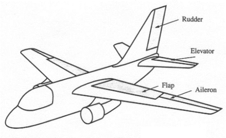
The ailerons control roll, elevators control pitch up and down and the rudder controls yaw left and right.
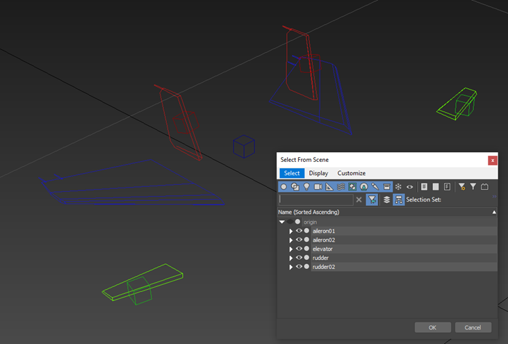
This image shows a full set of flight control surfaces in 3ds Max (Ailerons in green, rudders in red, elevator in blue). Ailerons rotate around the Y-axis, elevators also rotate around the Y-axis and the rudders rotate around the Z-axis. You can have up to six ailerons, six elevators and six rudders per vehicle.
Vehicle Damage
As a vehicle becomes damaged, the game code can un-hide particular bones in your model. This can be used to show damage by attaching emitters to those bones since emitters in the model will start emitting when the bone they are attached to becomes un-hidden. There is support for three stages of damage, activated when the model reaches 25%, 50%, and 75% damage. When the model loses 25% of its health, all bones whose names begin with DAMAGE25 will be un-hidden. Once the object has lost 50% of its health, all bones whose names begin with DAMAGE50 will also become un-hidden. And when it has lost 75%, the DAMAGE75 bones will un-hide.
Inverse Kinematics
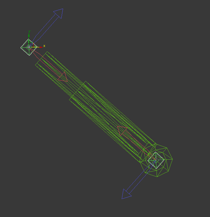
Vehicles can have a simple inverse kinematic system, with a maximum of 4 pairs of bones. This can be used for hydraulic systems on vehicle turrets, recoil hydraulic absorbers, etc. The system will rotate the two bones along their Y-axis so that they will always point at each other along their X-Axis. To set this up, have two bones, with the same root name and either IK0 or IK1 at the end. For example, in the below image, the two selected bones are named hyd_ik0 and hyd_ik1. They face each other along the X-Axis (the red arrow) and they rotate along the Y-axis (which points out of the screen in this side on view). These bones can't be parented to each other, but they can be parented to objects in the scene. For example, in the image, the top IK bone is parented to a barrel bone and the bottom IK bone is parented to the chassis, This will allow the hydraulics in the model slide in and out properly as the barrel pitches up and down.
Physics Parameters
All of the actual physics parameters are controlled through the Mammoth level editor. When creating a vehicle, the first thing you have to do is choose the physics model that it will use. There are five main physics models for vehicles: WheeledVehicle, TrackedVehicle, Motorcycle, VTOLVehicle and AircraftPhys.
Parameters common to all vehicles
- Mass - the mass of the vehicle
- GravScale - a scale factor that is applied to the gravitational force on the vehicle. This is set to 2.25 for most vehicles.
- Elasticity - not currently used.
- AerodynamicDragCoefficient - controls the amount of drag.
- Spring Constant - spring constant for the suspension (even VTOL vehicles have a suspension)
- Damping Constant - damping in the suspension springs
- Spring Length - suspension length, wheels start at their initial position and can translate down this far
- Traction Multiplier - scales the amount of traction available to the vehicle
- Lateral Moment Arm - length of the rotational moment arm for lateral forces at the tire contact patches. this lets us fake the lean of the vehicle when turning without having to adjust the W3D model.
- TractiveMoment Arm - length of the rotational moment arm for tractive forces at the tire contact patches. This lets us control how much the vehicle "dives" when it brakes and how much it leans back when accelerating.
- EngineFlameLength - if the vehicle has an "EngineFlame" bone, this controls how far that bone will translate. Since this parameter is available to all vehicles (not just the Orca), we could create things like Recon Bikes and cars that have a flame emitting out of their engine.
Parameters specific to ground vehicles
- MaxEngineTorque - this is the torque that the engine can output. For tracked vehicles we don't have a sophisticated engine simulation; this torque is simply divided between the wheels and applied (also scaled by user input)
- EngineTorqueCurveFilename - this is the engine torque curve (relates torque to engine RPM). These curves are created with the "SimpleGraph" tool
- Gear Count - number of gears in the transimission
- GearRatio[0-6] - transmission gear ratios
- FinalDriveGearRaio - gear ratio in the differential
- DriveTrainInertia - inertia in the drive train components
- ShiftUpRpms - point at which the code shifts into a higher gear
- ShiftDownRpms - point at which the code shifts down to a lower gear
- MaxSteeringAngle - maximum angle of the steering tires
- LeanK0 - internal torsional spring constant for motorcycle "balancing"
- LeanK1 - internal torsional damping constant for motorcycle "balancing"
Parameters specific to VTOL (Vertical Take-Off and Landing) vehicles
- MaxHorizontalAcceleration - acceleration of the vehicle in the X-Y plane
- MaxVerticalAcceleration - acceleration of the vehicle along the Z axis
- MaxFuselagePitch - angle that the vehicle pitches when acclerating forward
- MaxFuselageRoll - angle that the vehicle rolls when strafing or turning
- PitchControllerGain - spring constant for the pitch controller
- PitchControllerDamping - damping constant for the pitch controller
- RollControllerGain - spring constant for the roll controller
- RollControllerDamping - damping constant for the roll controller
- MaxYawVelocity - how fast the vehicle can spin
- YawControllerGain - how fast the vehicle reaches its MaxYawVelocity
- RotorSpeed - how fast the 'ROTOR' bones should spin
- RotorAcceleration - acceleration of the 'ROTOR' bones
- RotorDeceleration - deceleration of the 'ROTOR' bones
- RotorBlurThreshold - determines the angular velocity at which RotorA/B bones are swapped.
Parameters specific to Aircraft
|
Parameter |
Default |
Short Description |
|
|
0.0 |
Maximum thrust produced by the engine |
|
|
0.0 |
Maximum reverse thrust, used for reversing on the runway (not realistic, but necessary) |
|
|
0.0 |
Sets the throttle response speed, i.e how quickly we can throttle from 0 to 100% and back |
|
|
0.0 |
Sets an upper limit on the maximum speed of the aircraft |
|
|
0.0 |
Sets the rotation intensity for pitch |
|
|
0.0 |
Sets rotation damping for pitch, limits maximum pitching speed |
|
|
0.0 |
Sets the rotation intensity for roll |
|
|
0.0 |
Sets the rotation damping for roll, limits maximum rolling speed |
|
|
0.0 |
Sets the rotation intensity for yaw |
|
|
0.0 |
Sets the rotation damping for yaw, limits maximum yaw speed |
|
|
0.0 |
Lift coefficient, higher value means aircraft can achieve the same lift at a lower speed (i.e stay in the air while moving slower) |
|
|
0.0 |
Sets the strength of the brakes, helps stop faster on the runway |
|
|
0.0 |
Sets the maximum speed at which the aircraft can move when the landing gear is deployed |
|
|
false |
If set to "true", aircraft's wings are assumed to be dihedral, which means they automatically try to level out the plane if its wings are not parallel with the ground |
|
|
0.0 |
Sets the intensity of roll stabilization (see: DihedralWings) |
|
|
30.0 |
Sets the maximum angle that the aircraft's flaps can be rotated to (should be kept between 0 and 45 degrees) |
|
|
25.0 |
Sets maximum engine rotation (for visual effects only) |
|
|
360.0 |
Sets maximum rotor speed (for visual effects only) |
|
|
180.0 |
Sets rotor acceleration (for visual effects only) |
|
|
180.0 |
Sets rotor deceleration (for visual effects only) |


Recommended Comments
There are no comments to display.
Join the conversation
You can post now and register later. If you have an account, sign in now to post with your account.