Search the Community
Showing results for tags '3 - Intermediate'.
Found 23 results
-
This will be the third video tutorial in a series about making maps. [PRIOR] First video tutorial: [PRIOR] Second video tutorial: [NOW] New video tutorial: Now get crackin' on those bases. Enjoy!
-
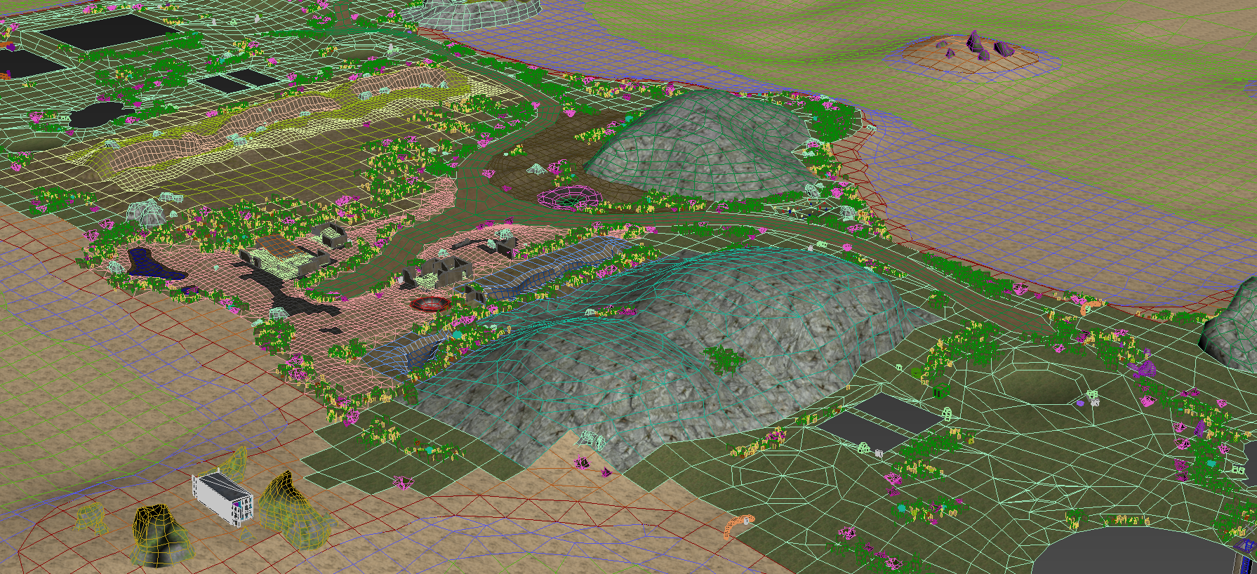
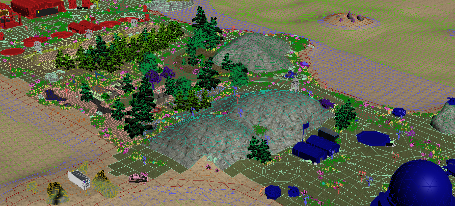
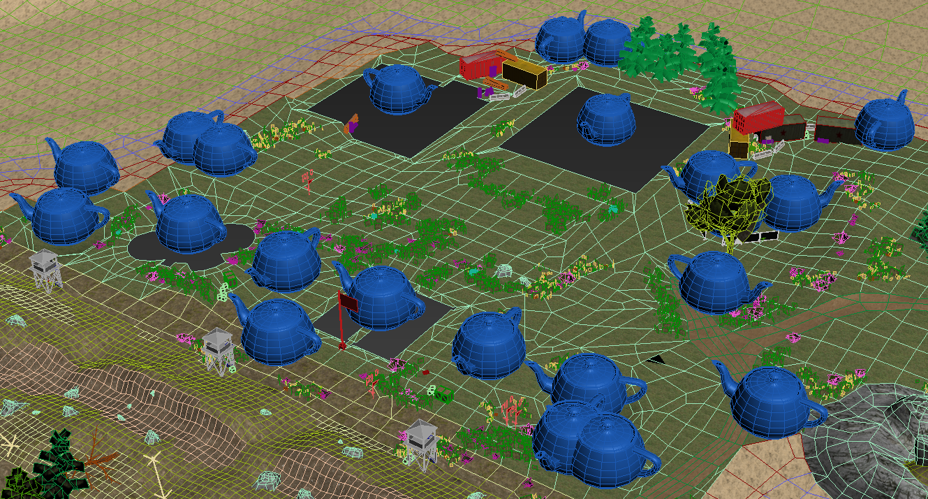
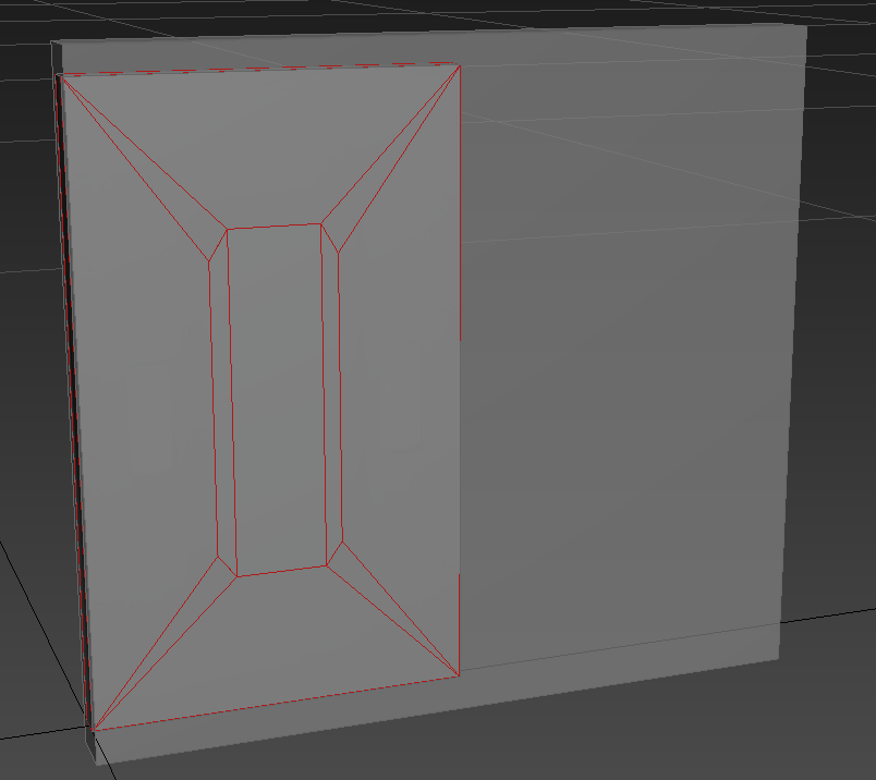
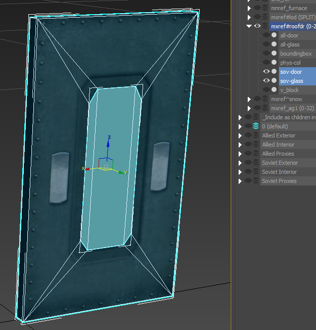
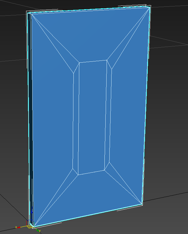
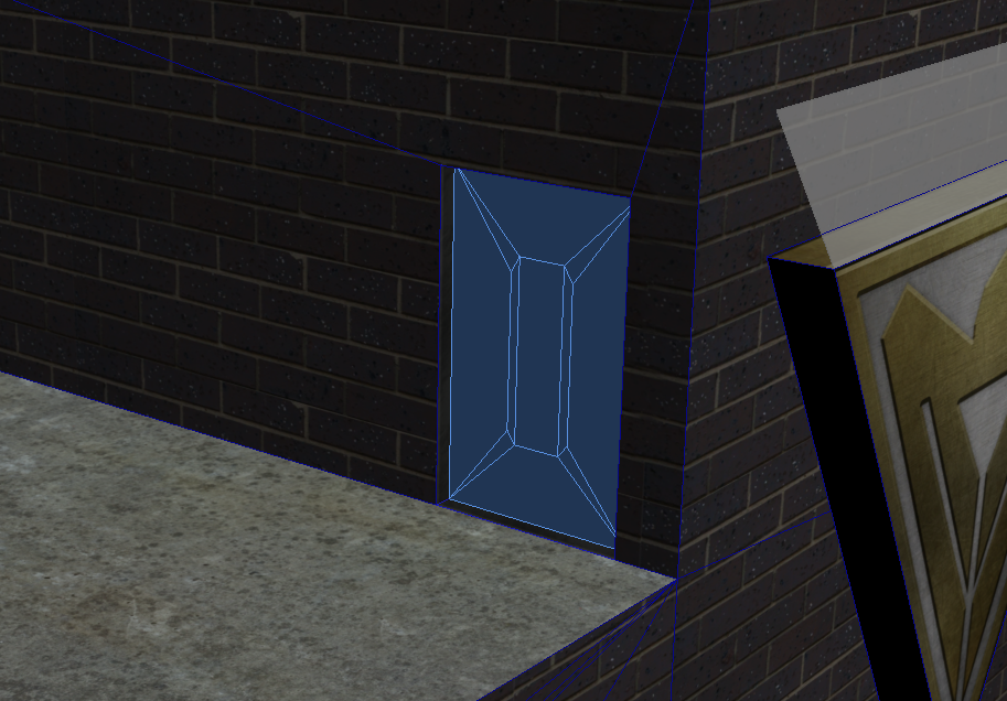
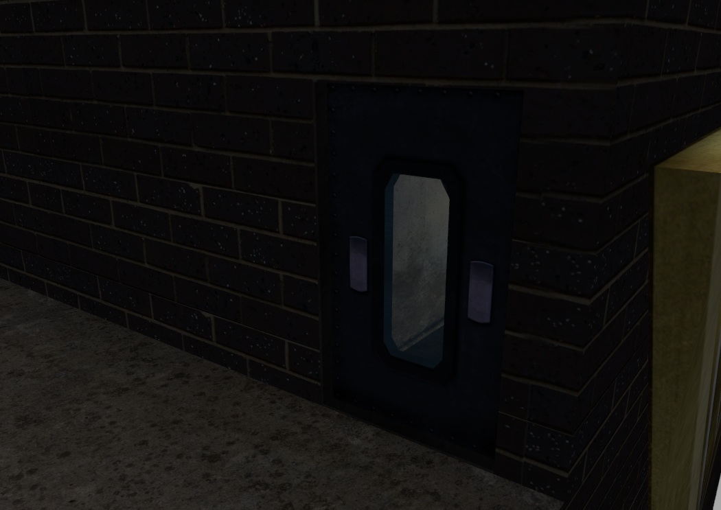
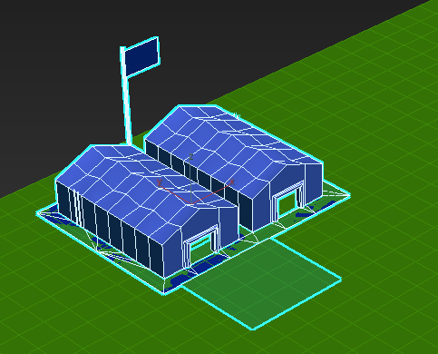
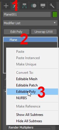
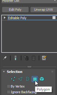
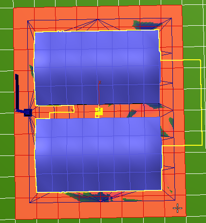
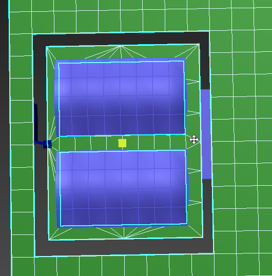
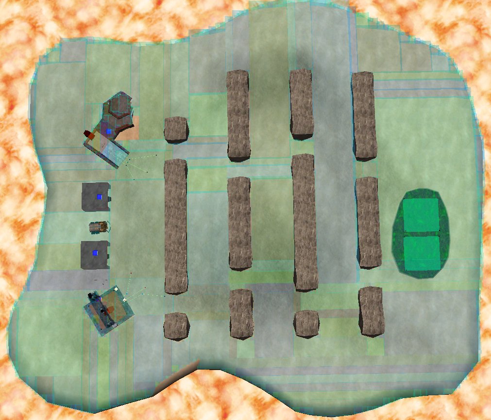
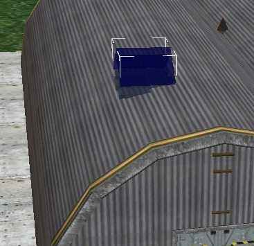
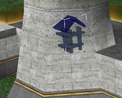
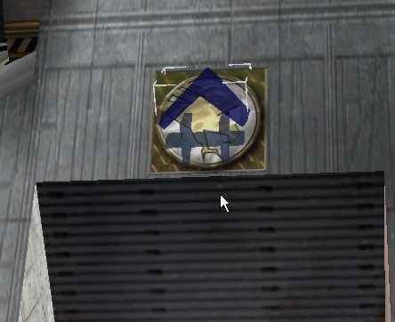
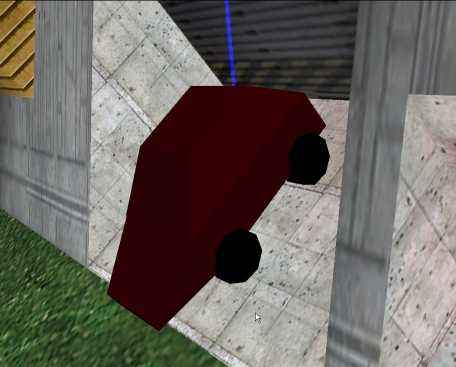
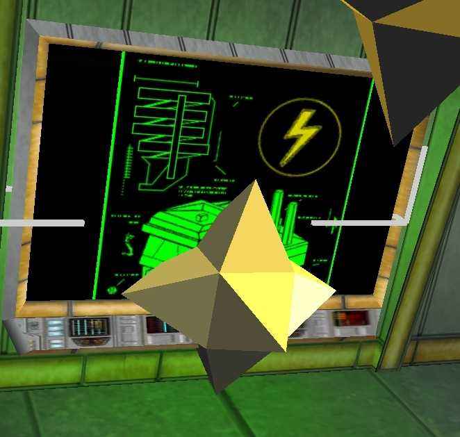
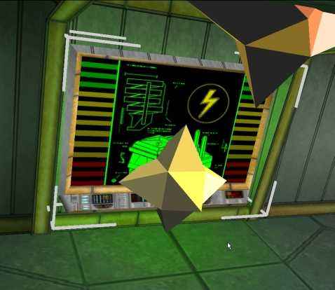
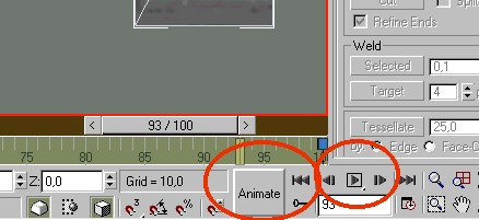
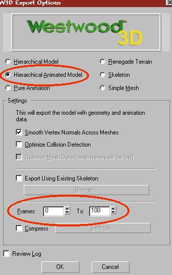
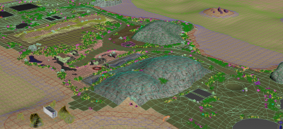
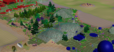
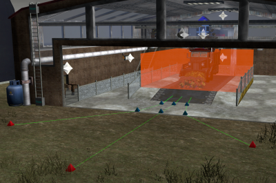
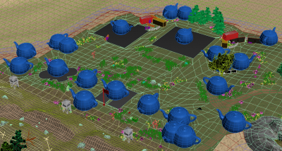
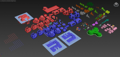
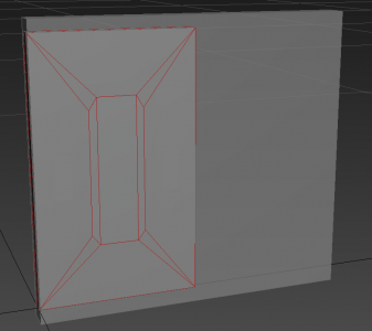
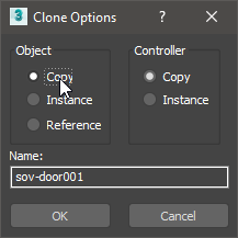
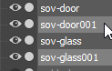
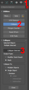
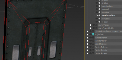
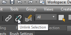
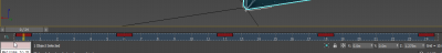
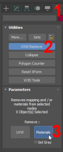
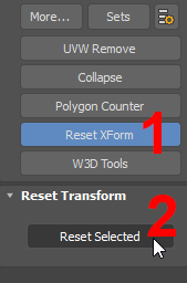
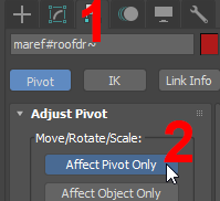
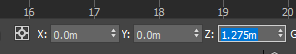
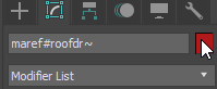
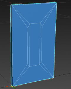
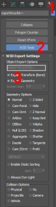
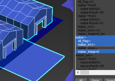
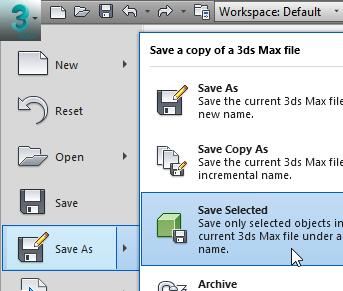
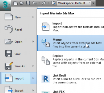
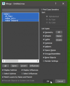
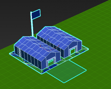
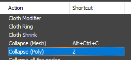
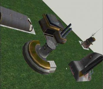
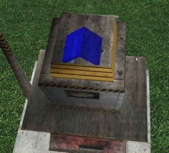
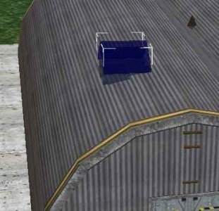
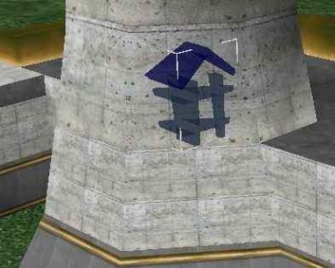
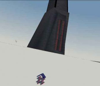
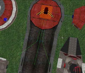
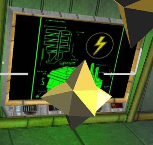
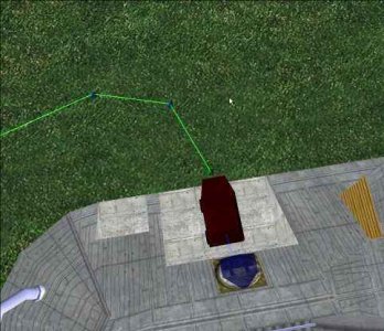
What is a proxy and how would it help in designing levels or assembling buildings?Proxies, at their core, are references to Mammoth presets that are placed on terrain pieces. I will repeat this later. First, let's establish the groundwork of how levels are put together. The main level terrain is built in 3DS Max and exported to a file with the extension "w3d." This terrain file typically includes all the ground, cliffs, caves, and a few other things (including proxies). Here are images of what is exported as the main terrain on Seamist, first shown without proxies, and then with. You can see we use them a lot! Once the file is built and exported, we use a program called Mammoth to make a preset that references this level terrain w3d file and places an instance of that giant map terrain piece on the level, so it starts as the main ground upon which everything else is built. After this point, we add everything else to the level that we want on it, which would include separate terrain pieces or tiles and various controllers that make everything work. Below is an example of some waypaths in front of a war factory that were added in Mammoth (and the little blue building icon near the top right was also placed in Mammoth). The building, lights, spawners, and orange construction zone were all "proxied in" as part of the terrain file, so we wouldn't need to add them manually to each level. How cumbersome that would be! In very old versions of APB, the main terrain file also included the actual buildings and trees, and some props would be placed using LevelEdit (the older program which Mammoth has now replaced). This led to problems and confusion in several ways. If actual buildings and trees are in the main terrain file, problems occur when those buildings and trees need to be edited or updated for any reason (the edit would need to be made, and then propagated manually to all of the buildings and trees in question on all of the maps that use them). In addition to this, if these are "baked terrain" as I'll call it, then there are also way fewer options regarding said objects. If objects such as trees, barrels, and rocks are placed on the ground in Mammoth, anything that's edited or placed on the terrain in 3ds max later on doesn't account for things that had been placed in Mammoth prior, so an interface disconnect takes place because those two very-related things would need to be edited across two different programs. For example if you place trees in mammoth, and edit the ground later in Max, then there are floating trees, sunken trees, or the trees could be merged with other objects that were placed there in Max. It would be an easy set of mistakes to make, and would simply be a frustrating way of doing it. LevelEdit/Mammoth simply isn't a very good program at the moment for placing and rotating objects, and painting objects isn't an option. It's a process that 3DS Max's UI handles much better. Inside the spoiler below is one example of painting tree presets (aka proxies) in 3DS Max. Nifty! As a result of the issues listed above, we use something called proxies. Proxies, at their core, are references to Mammoth presets that are placed on terrain. If I place a proxy on a map, it's just an object (no mesh or polygons) that tells the game to place this Mammoth preset at this location, and rotate/scale it in such a way. Currently we proxy our buildings, infantry spawns, purchase terminal pokes, trees, and anything else that we want to operate as references rather than "baked terrain" or placed manually using Mammoth. Again, with proxies/references we have a lot more options, it's a huge time saver, lends to consistency, and it gives us the freedom to edit that preset once, having it propagated automatically to all the places where the proxies have been placed. In Max, a proxy can look like a box, a triangle, a teapot, or literally anything you want it to be. In APB, we try our best to mimic the object that the proxy is referencing, while still making it obvious that the object is a proxy. It can be tempting to try to edit bits of the proxy object, thinking that it will edit the object's look ingame, but I want to make it clear that editing the proxy object won't do anything to affect the object's look ingame. All the game cares about is the location/rotation of the proxy object, not what it looks like. The preset will take care of what it looks like. Because all these giant blue teapots are named appropriately as the Soviet base buildings on Seamist that they are meant to represent, exporting this would yield a map that looks correct, with Soviet base buildings and not teapots. In APB's released SDK, you may find a file called that we named the "Proxy Masters" file. This contains a large set of proxies that we place around maps, and we use this file regularly to import those objects when designing levels, so we can easily place buildings, trees, and props. Here is what the file looks like at a glance. Currently some of the buildings have two copies because the extra copy is the tunnel version of the building. If you have ever used one of the w3d importers, you may find that it automatically turns all proxies into little yellow boxes, or some other form of Max primitive. This is consistent with the idea that the proxy objects/meshes don't matter, but the pivot point. However, it's best to try to represent the object that the proxy is referencing, so when it's placed on a level, it's easy to see at a glance what the object is and how much space it takes. For buildings, this is crucial if you need to cut holes in the ground around them. What is the best way to create a proxy object?It may be best to have a source file for the preset that you'd like to proxy, but if you don't, it is easy enough to use the w3d importer (and the w3d importer also guarantees that the origin/pivot is in the right spot from the get-go). Whichever way you do this, open up the file in Max. Today I'll make a proxy object out of this Refinery roof door. Your object is likely to have multiple meshes. Decide which meshes you want to be a part of your proxy object. You won't want to use bones, bounding boxes, or other things that don't show ingame. Select these multiple meshes that you've decided will be part of the proxy object. For me in this case, that would be sov-door and sov-glass. Use Ctrl + V to copy and paste (use copy, not instance) the meshes you want to be in your proxy object, then use "collapse" in utilities to merge the copied pieces all to one object. Now remove or hide the original meshes so only your new collapsed object is showing. Name this new object with the preset name that mammoth uses, and then put ~ as the suffix. E.g. if the preset in Mammoth is named t_pine, then the proxy object should be named t_pine~. Any characters after the ~ won't factor in to the preset's name, but will work to export multiple copies or instances or the proxies. If you had a pine tree preset in mammoth named f_pine, the placed proxies could be named f_pine~00, f_pine~01, etc. Or if you wanted to make the pine trees different scales, you would put a $ at the start, e.g. $f_pine~00. Unlink the object if it is parented to anything. Only if the object is animated: remove any animations that might be tied to the object. First make sure your animation slider is at frame 0, then drag a box over all keyframes and press delete key to remove them. Remove all materials from the object. With it selected, press the buttons in the image below. Reset xform, and right click on the object -> convert to editable poly. The pivot now needs to be at location 0 0 0 on XYZ (a.k.a. the origin or middle of the grid). We can see below that it's not already at the origin, so we'll need to move it there. Uncheck pivot only so you go back to normal editing mode. Assign any object color and layer for organizational purposes. Typically we try to choose colors that make the most sense, e.g. blue for Allies, red for Soviets, green for trees, etc. Note * 2, I realize I used the Soviet doors to make the Allied proxy, but the fun part is that it doesn't matter! Oftentimes we'll also assign a special layer for our proxies. Buildings are on the buildings layer, Trees are on a Foliage layer, and props that are proxies we typically just put in the Props or Proxies layer. However you want to do it that best suits your workflow, is how you should do it. You can remove all collision settings, but make sure export transform (bone) and geometry are both checked. Now with this door, I can place it exactly where in the building I want that door to be! Left: Door proxy placed in 3DS Max, Right: How it appears ingame. What is the best way to place proxies on my level terrain? There are different kinds of proxies to place on levels. Let's start with base buildings. Open the proxy masters file. Assume we're placing an Allied Barracks. Select the barracks, then open the object list with H and select everything underneath it in the hierarchy that you would like to copy over to your level. Hit select, then File -> Save As -> Save Selected. I typically just save Untitled to desktop. Now open your level file in Max, go to File -> Import -> Merge (I set this as a shortcut key Shift + M since I use it so often). Select the Untitled file from the Desktop, then select all objects and hit OK. The Barracks will appear. If you did nothing else at this point and exported your map, you would have a Barracks there, but do note you wouldn't be able to travel between the floors because no hole was cut in the ground. This placement method can be done with any of the buildings, trees, or other proxies that you wish to use from the proxy masters file. BONUS ROUNDI know this isn't about proxies, but so that we put a nice pretty bow on things, let's cut a hole in the ground for the Barracks. If your terrain isn't already editable poly, convert it to that. Now press 4 or click on the little polygon icon to activate polygon editing mode. Select the polygons that fill the Barracks area and press Del to delete them. Now, get out of polygon mode (press 4 again) and attach the temp ground (which notably isn't a proxy) to your ground plane. Now, go to Vertex mode (press 1) and start welding/collapsing these separate pieces together for each vertex. I set up a keyboard shortcut to help do this quickly. Customize -> Customize UI -> Collapse (Poly) set to button of your choice. Once it's welded all the way around you should have your hole cut for your proxied Barracks, and the basement should be accessible. That's about it for now, folks! Notes: - The game doesn't care about what your proxy mesh is, it only cares about the pivot and its location and rotation (and sometimes scale). - For objects to export from Max, there is a character limit of 15 characters, which means you want relatively short preset names if you want to proxy those presets. 10 characters would be a safe upper limit for preset names, so the limit would account for a $ prefix, the ~ suffix, and would support hundreds of that proxy object. - Proxies only work if you place them in terrain objects, not if you place them on hierarchical tiles or other simple objects/vehicles that you make. - APB's buildings are proxied terrain objects which proxy yet more objects. This means proxying can be nested as long as all the proxy objects exist in terrain presets.


-
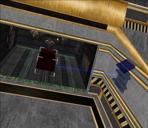
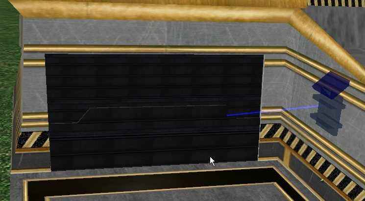
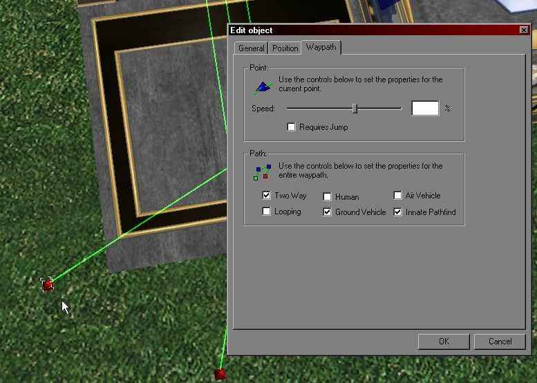
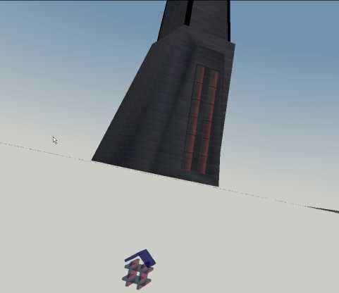
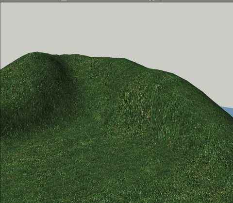
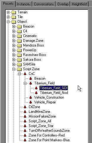
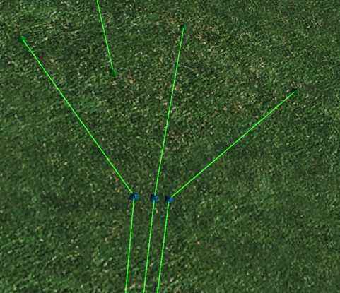
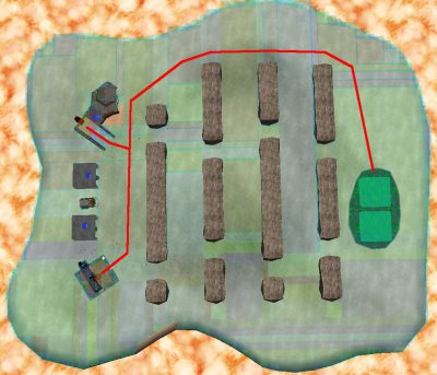
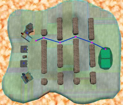
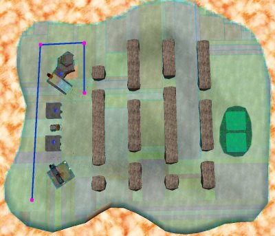
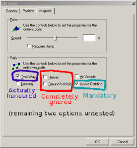
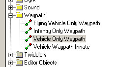
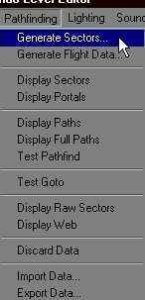
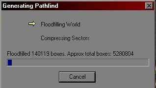
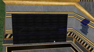
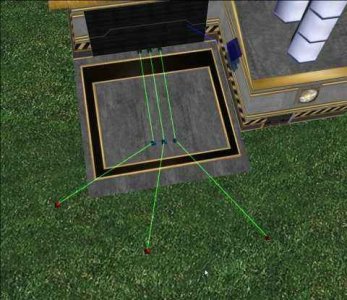
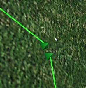
 Prerequisites First read and follow Laubi's original tutorial on "Harvester AI Pathfinding" (W3Dhub link). This tutorial has been around for a very long time. The attached "harvtest_paths.zip" file contains three example .mix maps for you to try out, each one is mentioned in the appropriate sections below. To play these you need to: Extract the .mix files to your Renegade/Data/ folder (typically C:\Westwood\Renegade\Data\) Start Renegade Choose "Host a LAN game" Change the settings to be: Max players = 1 Dedicated = no Map rotation = any one of these three maps Between the buildings on the map is a flying harvester that you can enter. Flying above the map makes it easier to see what is going on. You should be running an up-to-date copy of TT/scripts and the latest version of Leveledit (not the version shipped by Westwood, see the TiberianTechnologies website). It contains several fixes that may affect how well you can follow the techniques in this tutorial. Introduction We're on an island floating far above a lava ocean. On one side of the island are the Nod & GDI bases, on the other far end is the tiberium field: In between the two bases is a maze with many possible routes for the harvesters to take First: setup your map as normal (and as per Laubi's tutorial), but don't create any waypaths for the harvesters just yet. Make sure to place the "Human" pathfind generator and generate pathfinding sectors for your map. In LevelEdit you can show the generated sectors using the menu item Pathfinding->Display Sectors: Note the greeny-blue boxes that appear. Each one is a 'zone' that objects can travel within, and each connects to the sectors that touch it. Objects in the game work out how to get from point A to point B by following a chain of these sectors. You do not actually need to create waypaths for your harvesters Despite all of the traditional advice: harvesters do NOT need waypaths. They can find their way to the fields and back all on their own using the pathfinding sectors. The only waypaths you need on your whole map are the short ones exiting your Weapons Factory and Airstrip, so that vehicles drive out a little after being created. By default harvesters always start in this 'self-navigating' mode once they leave the WF/Air. They only start using waypaths when they "accidentally" encounter one whilst driving (and several other conditions are met, described later in this tut). If you don't believe me: try it. According to JonWil there is no special code (in Vanilla Renegade harvesters) for handling waypaths. My understanding is that they incidentally can use waypaths because the W3D engine's normal innate pathfinding code (used by all AI) handles using waypaths. On the example map for this tutorial: harvesters are picking a non-optimal route when left to work things out on their own: Try the map C&C_Harvpath_nopaths.mix to see this yourself. How do harvesters "enter" a waypath? (1) When a harvester is created: it uses the pathfinding sectors to find its own route to the tiberium field (or other destination) and starts on this route. (2) Every time the harvester enters a new sector it checks to see if there are any waypaths that start in this sector. A harvester will only follow one of these detected waypaths if multiples conditions are met: The path is of type 'innate' The end of the path is closer to the harvester's target than where the harvester currently is. (Possibly some distance or number-of sector metrics, unknown) Once the harv starts following a waypath it will not leave it until the path ends. How do I design my waypaths? First find the path your harvesters take on their own. Play your map in-game to find out. Next create a path that starts from one of the sectors your harvester crosses. End this path near (or closer to) the tib field: Try the map C&C_Harvpath_Pathed.mix to see this working. Both harvs end up getting caught by the one path in this example (but you generally want to add separate paths for each), and the path is not perfect so they start grinding against the walls. You can use any type of waypath provided in LE, they're all the same: I actually use the 'flying vehicle only waypath' just to make people feel unsettled. The only requirements are that you change the waypath settings to enable 'Innate Pathfind' after you create it. You get to this dialog by double-clicking a node on the waypath (not the line part of the path): Two-way is an option that is legitimately accepted by the game and useful to consider. The Human/Ground/Air fields appear to do nothing at all, you can even un-tick them and your harv will still follow the path. You do NOT need to re-calculate pathfinding after making or changing any waypoints. Waypoints are a separate part of the system that are handled during map export (to .MIX). This feature may be buggy in older versions of LevelEdit. Here's an example of a waypath that will NOT work. Note that the path now starts in the doorway of the maze, rather than in the sector outside of it. The harvesters never cross the pathfinding sectors in this doorway, so they never 'see' the path: They may however 'see' this path on the way back from the tiberium field, assuming the path has been marked as Two Way. Harvesters will use your path as long as (1) you start the path in a sector the harvesters already drive over, and (2) end the path closer to the goal than it starts. This means that you can give them really stupid long routes and they will still follow them, such as this: Try the map C&C_Harvpath_Stupid.mix to see this yourself. Note that one of the harvesters takes a 'shortcut', I am uncertain of the exact logic behind this, but I believe it notices the nearby waypath nodes when it crosses sectors whilst leaving the Weapons Factory. If we were to end the path at a position further from the tib field than where we started then the path will NOT be accepted/chosen by the harvesters: (They could potentially choose this path on their way back, however, as its end may be nearer their "goal" (eg the GDI refinery) than their current position). Conclusions Confusions, comments or problems? Ask below or on the main W3Dhub forums. Areas that are still not understood: Whether or not this 'innate pathfinding' is exactly the same for all AI in the game, or slightly different for harvesters. What metric is used to make choices on route. Eg minimising distance travelled OR number of sectors travelled through? How harvesters start waypaths at points other than their ends (ie take shortcuts) harvpath_tests.zip
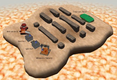


-
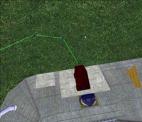
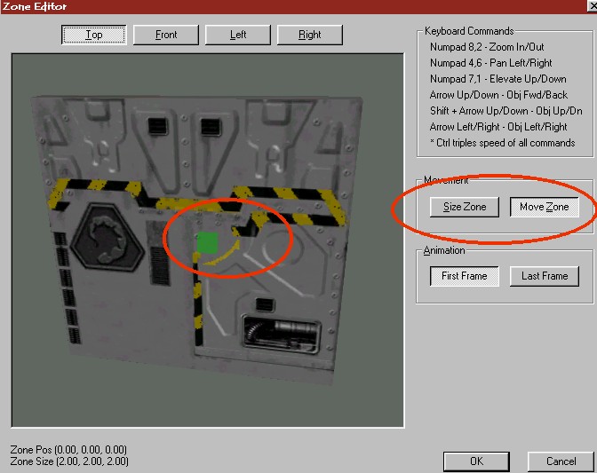
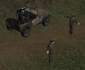
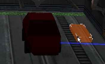
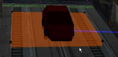
Author: moonsense715, dblaney1 Skill level: 3 Enter zones The character position doesn't matter here. Players must be inside the enter zone to enter the vehicle. Suggestion: make the zone cover the entire vehicle, plus a big enough area around it in which players are allowed to enter from. One zone is enough for entering. Exit zones The players will exit the vehicle at the character position. The exit zone must contain the position of the seat bones. Note: The zones rotate on the Z axis but not on the X and Y ones. This explains why a vehicle sometimes cannot be exited when it's on a slope, since the seat bone is out of the zone due to no x/y rotation following of the zone. Suggestion: Make the zone even bigger than the enter zone. There can be multiple exit zones for a vehicle. If one is blocked by other objects, the next one will be tried and so on.
-
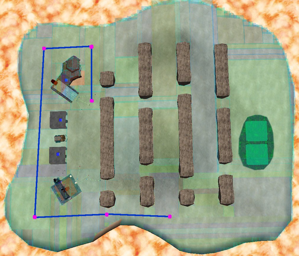
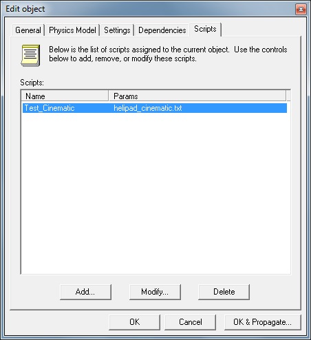
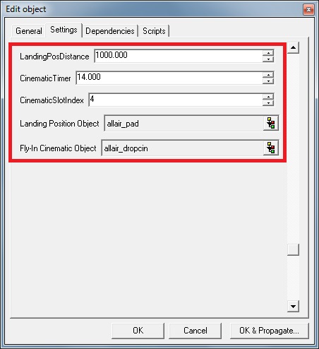
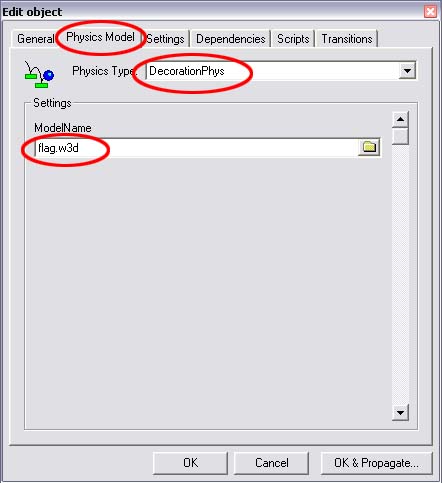
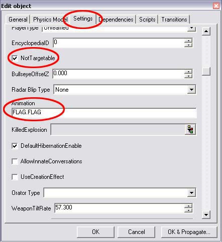
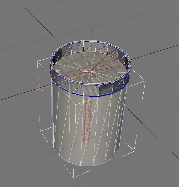
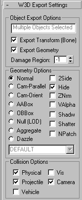
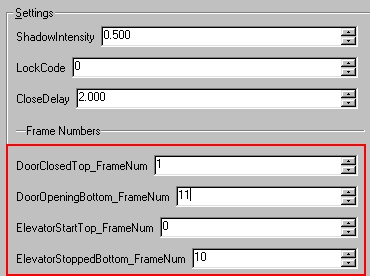
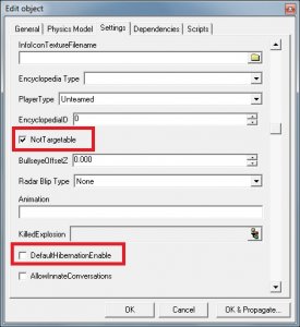
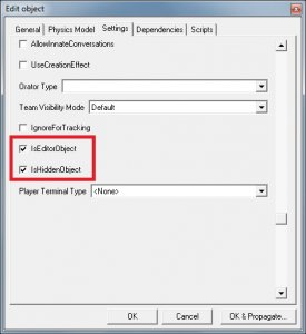
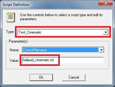
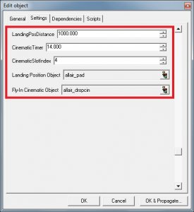
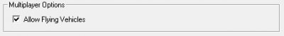
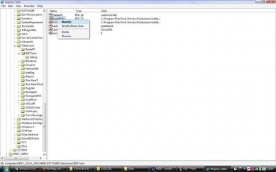
Author: Jonwil, Generalcamo Skill level: 3 This tutorial will show you how to make functional helipads and make the helicopters arrive to the helipad and link them to it instead of the War Factory. Note: It will be totally separate from the weapons factory/airstrip in that you will be able to buy helicopters even if the war factory/airstrip is down and you will be able to buy ground vehicles if the helipad is down. You can even have someone buying a helicopter and someone else buying a ground vehicle at the same time. 1. Setting up the sidebar Firstly, in order to use this functionality you need to be using the sidebar in your map. Follow this tutorial (https://secure.w3dhub.com/forum/index.php?showtopic=414727) to set up the sidebar. You also require a scripts build that supports this feature. Copy its content to your game folder (not Data) and overwrite all. Also copy ttle.dll, memorymanager.dll and shared.dll to your root LevelEdit folder, where LevelEdit.exe is sitting. Restart LE if it was running. 2. Prerequisites You also need to include a helipad_cinematic.txt (you can give it a different name) file and xg_hd_htraj.w3d in your map mix file or always.dat. Open the C&C_MyMap_tt.ini file you made in the sidebar tutorial and add the following: VehicleFactoryVehicleLimit=10 AirFactoryVehicleLimit=6 If you want to set a global limit that applies to all maps, put these into tt.ini instead of the mapspecific ini file. This sets the limit of the vehicles and helicopters players can buy, feel free to change these limits. 3. LevelEdit work To set up the helipads, first you need to put a building on your map to act as the helipad. Create it like any other building (give it MCTs, PTs, damage aggregates and whatever else you want for it) Then open leveledit and open your map. 3.1 Cinematic preset Create a new preset underneath "simple". This will be the helipad fly-in cinematic object. Untick the "DefaultHibernationEnable" checkbox. Tick the "NotTargetable" checkbox. Tick the "IsEditorObject" checkbox. Tick the "IsHiddenObject" checkbox. Leave all the other settings at the default. Attach the script Test_Cinematic to this object and give it the parameter helipad_cinematic.txt 3.2 Landing object preset Next, you need to create a landing position preset with whatever name you like. This will determine where the helicopters will fly in at and do nothing else. You will need one preset for each team (the fly-in cinematic preset is used by both teams). Make this one a copy of the Dave's Arrow preset with no changes to the settings and you are done. Now you should have the presets ready that can not be seen ingame but act as the landing position. If you can't find a Dave's Arrow preset, don't panic. This preset is used to place objects in LevelEdit that do not appear ingame. You can make one by creating a simple object, DecorationPhysics type and the model is o_davesarrow.w3d. On the settings page, tick IsEditorObject, untick DefaultHibernationEnable and you are done. 3.3 Building preset Next, go to buildings and then air factory. Create an instance of this (one for each team). If you dont see air factory in the list it means you dont have 4.1 installed properly. Set this preset up as for any other building with all the usual settings and scripts you want. Make sure to set the building type to "helipad" Set LandingPosDistance to 1000 Set CinematicTimer to 14.0 Set CinematicSlotIndex to 4 Set Landing Position Object to the landing position object preset created earlier. Set fly-in Cinematic Object to the fly-in cinematic object preset created earlier. No special scripts are required for this building. Once you have done this, place the helipad building controllers as per normal for buildings. Then place several (2 or 3 works good) of the landing position objects (for the right team) around the helipad at ground level. (these will determine where the helicopters land at). You can't have more than one helipad per team, the logic doesn't support it. Now you need to set up the war factory/airstrip to not build helicopters anymore and to have them be built at the helipad. If you have helipads on an individual map, create temp presets of the war factory and airstrip (or if you are already using temp presets, open them). If you are making a full game, mod the normal presets. The only change you need to make is to tick the BuildGroundOnly checkbox. 4. Finishing touches For all maps using the helipad, you need to tick the allow flying vehicles checkbox under edit-level settings in LE. Note: this tickbox does not need ticking at all from scripts 5.0 onwards. Do not forget to set a proper flight roof (blocker) or the players will be able to fly out of the map.


-
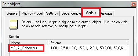
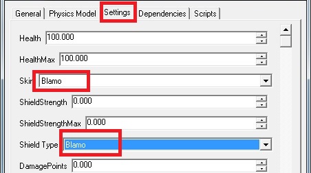
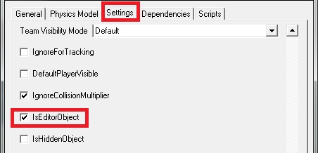
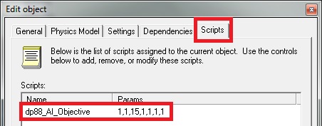
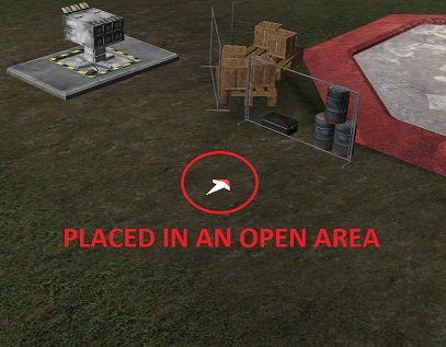
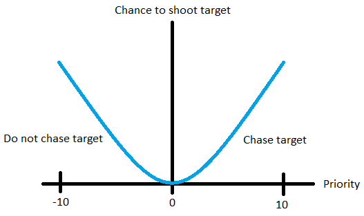
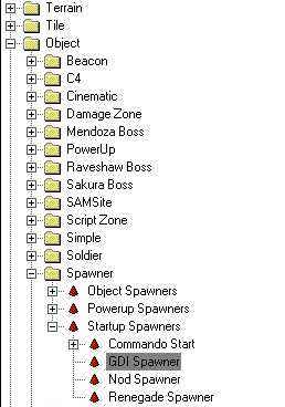
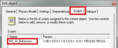
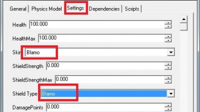
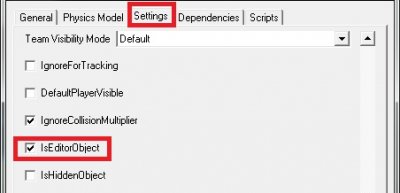
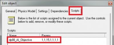
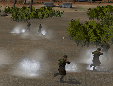
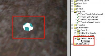
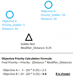
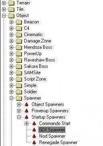
Author: moonsense715 Skill level: 3 Welcome to the first chapter of the tutorials that will show you how to add and configure more sophisticated bots to your maps. In this lesson, we will place a few very simple bots and give them objectives to do. They won't shoot regular base buildings or do anything too interesting for now. Optionally, you can also learn how to fine tune objectives and bot behaviour. - Wait, what are bots?! Bots are computer controlled objects (characters, vehicles) that do a task given to them. They don't need an actual human player to control how they behave. The most typical bots in a lot of W3D games are the mobile resource collector vehicles (Ore Truck, Tiberium Harvester) and the static base defenses (turrets, pillboxes, obelisks, sam sites). 1. Setup bot presets Start the Level Editor if you haven't already and open your project. Make sure you have generated pathfinding! In the preset tree, go to Objects -> Soldier, and click on a soldier preset you would like to appear on your map as a bot. Then, click Temp. (Note: if you are making a .mix map for a game, always use Temp to add new presets. If you are editing a game core so the presets are available on every map in the game, use Add! In case you are creating a standalone .pkg map, you can use both.) Give this new preset a name (for example MyAwesomeBot). We will use a script to apply the AI. Switch to the Scripts tab. Add the script MS_AI_Behaviour to the list and hit OK. Don't modify the parameters for now. Click OK again to finish your new bot preset. Create another temp preset by doing the same steps again, but this time, pick a soldier preset from the other team, so they can fight eachother. If you want to go a little further, pick 1-1 vehicle preset as well for both teams and do the same steps to have a few bot vehicle presets set up. Now that you have the presets ready, let's place them. Click on each preset and hit Make. You can move them around after placing to change their position. I recommend you place the bots into their own bases, but at least keep the two teams away from eachother if there are no bases on your map. If you want the bots to respawn after dying, you'll need to create spawners. Please read the spawner tutorial here. (You will need to place new spawners and delete the placed presets, since the spawners will create them dynamically.) You're done setting up and placing your bots! 2. Add AI Objectives Without objectives, bots will just wander around the position where they started and shoot enemies they see. You will want to give them objectives to run to and find, positions to defend, buildings or vehicles to attack. This is done by creating AI Objectives. Alright, you have your bots sitting in their bases. If you export and play your map now, the bots will shoot enemies that get close to them, but they will not do anything specific otherwise. To change this, we will tell them to run into the enemy base! First, let's create an objective for Team 1. For this tutorial, this is going to be the Allied team, while Team 0 is the Soviets. On the preset list, scroll down to Simple and Temp it. Give it a name, e.g. MarkerObjectiveAllied. On the Physics Model tab, pick a w3d model's ModelName, e.g. o_davesarrow.w3d. Go to the Settings tab, make sure IsEditorObject is ticked, so this model can only be seen in LevelEdit. Also make sure the object cannot die, set the Skin and Shield Type to Blamo (if there is no Blamo, pick one that is invulnerable to attacks). Switch to the Scripts tab and attach the script dp88_AI_Objective. This is the marker that tells bots "Come closer, your objective is here!" The preset we are creating is the "host" of the objective script, we will place it somewhere on the level so bots know where the objective is. Note that this is not the target that they will shoot, just a go-to location. This particular objective will be permanent and will not change position during the game. Now, set up the parameters like so: Team: 1 (= Allies/GDI) Type: 1 (= Offensive) Range: 15 Priority_Soldier/Light_Vehicle/Heavy_Vehicle/Aircraft: 1 (set all of them to 1) Place this marker in the Soviet/Nod base somewhere on open ground (not inside a building). Now the Allied bots will know where the Soviet base is, and they will keep running here. What about the Soviets, you might ask? Well, let's not let them down, and add an objective for them too. Do the same steps you did for the Allied objective, but this time, make sure the Team parameter is 0 and that you place the object in the Allied base. Good job! If you go ingame now, the bots will run to eachother's base and shoot enemy characters and vehicles. 3. Optional: Dynamic AI Objectives, Priorities Static objectives, the ones we placed is one thing, but let's see what else we can do here. In LevelEdit, place any vehicle object or vehicle spawner on your map, so that you can drive the vehicle ingame. Now, double click to edit the vehicle object that you placed in the scene, or edit its preset in the preset tree (only if it's a Temp preset!). Add the dp88_AI_Objective script for Team 1 on the Scripts tab with the same parameters as before, but change the Priority_Soldier parameter to 100. Head ingame and test your map, play as Soviets (team 0). Enter the vehicle you edited and drive around ingame, somewhere away from your base. You will notice that the Allied soldier bots will run after your vehicle and find you no matter where you are (as long as you are within the pathfind grid). Now you know how to tell bots to find a moving object. This can be very useful if you know what you want to do in your map/game. If there are multiple objectives for the same team on a map, the bots will consider 2 things: What's the priority of the objective? If two objectives are roughly the same distance away, the higher priority one will be picked. How far is it from their current location? If two objectives have the same priority, the one that's closer will be picked. After analyzing, each bot will choose the optimal objective. For example, they will most likely pick an objective 10 meters away with priority 1 instead of another one 100 meters away with priority 2. If the priority calculation for a particular objective ends up being negative (e.g. priority too low or distance too high), it will be treated as a 0.0001 priority objective (so it's positive). Keep this in mind when setting priorities for multiple objectives, as they can end up being the same value. Note: after a bot chooses an objective, it will not change it, not even if a higher priority one appears. It will keep its chosen objective as long as the script-wielding object is alive or until dp88_AI_Objective is removed from it by other scripts. 4. Optional: Bot Targeting Priorities Remember in the first steps, when we attached the script MS_AI_Behaviour but did not touch the parameters? Let's look at them now. The priority system was created by @danpaul88, and lets you tell your bots what to shoot, how to shoot them, and in case of multiple targets, which one to shoot at first. MS_AI_Behaviour implements this system. The full description of the parameter list is here: Priority_Infantry: Base targetting priority for infantry targets, or 0 to ignore infantry Weapon_Infantry: Weapon to use against infantry targets: 1 for primary fire, 2 for secondary fire Splash_Infantry: Determines if we should try to damage infantry with splash instead of hitting them directly. This is useful for slow / inaccurate weapons which do splash damage: 1 to enable, 0 to disable Priority_Light_Vehicle: Base targetting priority for light vehicle targets, or 0 to ignore light vehicles Weapon_Light_Vehicle: Weapon to use against light vehicle targets: 1 for primary fire, 2 for secondary fire Priority_Heavy_Vehicle: Base targetting priority for heavy vehicle targets, or 0 to ignore heavy vehicles Weapon_Heavy_Vehicle: Weapon to use against heavy vehicle targets: 1 for primary fire, 2 for secondary fire Priority_VTOL: Base targetting priority for flying targets, or 0 to ignore flying targets Weapon_VTOL: Weapon to use against flying targets: 1 for primary fire, 2 for secondary fire Priority_Building: Base targetting priority for building targets, or 0 to ignore building targets Weapon_Building: Weapon to use against building targets: 1 for primary fire, 2 for secondary fire Max_Attack_Range: Maximum distance at which the unit can engage enemies when using primary fire Min_Attack_Range: Minimum distance at which the unit can engage enemies when using primary fire Preferred_Attack_Range: Preferred minimal distance, the unit will try to move within this range when using primary fire Max_Attack_Range_Secondary: Maximum distance at which the unit can engage enemies when using secondary fire Min_Attack_Range_Secondary: Minimum distance at which the unit can engage enemies when using secondary fire Preferred_Attack_Range_Secondary: Preferred minimal distance, the unit will try to move within this range when using secondary fire Modifier_Distance: Priority modification to apply based on distance to target. Higher values will favour targets which are closer to the unit, good for less accurate weapons and slow vehicles Modifier_Target_Damage: Priority modification to apply based on damage a target has already sustained. Higher values will favour targets which have already been damaged in combat, picking them off first Modifier_Target_Value: Priority modification to apply based on the value of the target. Higher values will favour targets with a higher purchase cost, good for hard hitting weapons DebugDeprecated: No longer in use Detects_Stealth: Determine whether this unit can detect stealthed enemies or not: 1 to enable, 0 to disable ObjectiveType: What type of objectives this unit will run for, valid values are 1 (Offensive), 2 (Defensive) or 3 (Engineering). All non-flying vehicles are treated as light vehicle unless they have one of the marker scripts on them: dp88_AI_Marker_HeavyVehicle - Bots will use the Heavy_Vehicle preferences against them dp88_AI_Marker_Building - Bots will use the Building preferences against them dp88_AI_Marker_Repairable - All bots except Engineering bot types will ignore them It is important to know that NEGATIVE PRIORITY is usable for any target type. The more negative a type priority is, the more chance the bot will pick that as the target. When this happens, the bot will still shoot these targets, but they will keep running towards their objective and will not chase them. Here's an example: Object A: priority = 1 and Object B: priority = -2 ---> object B will be shot and the bot will move towards its main objective. If a target type should not be targeted at all, then you should use 0 as the priority value. For practice, try configuring rifle soldiers so that they will prefer shooting soldiers even when vehicles are within their sight range. Make tanks shoot other vehicles first and not chase soldiers (negative priority). Make them ignore aircraft. Last, come up with something that makes sense for a unit. E.g. anti-tank infantry, anti-aircraft vehicles, etc. Play with the priority parameters until you are happy with your bot behaviours. Please keep in mind that Objective Priorities and Target Priorities are completely separate things, even though both are affected by the Modifier_Distance parameter. Objective Priorities are for telling bots where to run when there are no targets around to chase, while Target Priorities are frequent calculations of enemies that the bot currently sees, and decides which ones to shoot/chase. That's it for the first lesson, now you should have a basic knowledge of how the new bot system works.


-

3 - Intermediate Quick tunnels with splines
Mauler posted a topic in Modelling, Unwrapping & Texturing
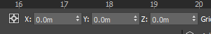
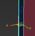
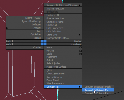
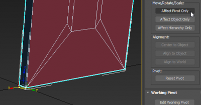
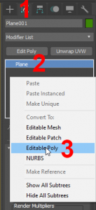
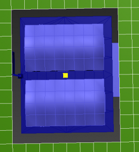
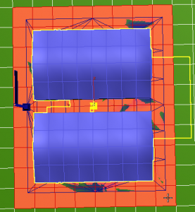
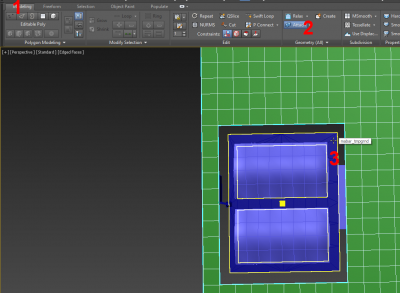
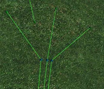
This tutorial is how to create natural style tunnels and man made style tunnels using splines. This method is very fast and makes modeling tunnels extremely fast and efficient. First create a spline with the line shape, this is in the 'Create' tab. Click on the 'Shapes' button and the Splines will show up. Click on 'Line' Start creating your tunnel shape. Here I am creating a linear tunnel that has sharp angles. More akin to man made tunnels. After finishing my spline shape, I will expand the 'Rendering' tab and adjust the spline for my tunnel mesh. Make sure to enable both render viewport and renderer. Then there is two choices of shapes of tunnel, radial and rectangle. Both have uses, here I am wanting more of a rectangle shape for my tunnel. I have set the scale to 6m by 6m. Totally up to you on your tunnel scales! You can also have rounded corners with the rectangular shape. Holding down the mouse button will create a bend. Releasing will continue linear shapes. Here I am using a radial shape instead for more natural type tunnels! Using the rounded corners can achieve great looking natural tunnels. Once you are happy with the shapes of the tunnels you can invert the mesh to give you a tunnel mesh! Simply convert to a editable mesh and select the mesh with the 'Element' button and it will select all polys, after that navigate to the 'Surface Properties' tab and click on the 'Flip' button under 'Normals' rollout. Repeat above step to achieve the same results on the man made tunnel! In conclusion, this tool is very powerful and can save hours of development time. This method is just a basic introduction to the splines. You can also edit the spline and have the tunnel follow the xyz coordinates to have multi-level tunnels that go up,down, and all around! Another great tool to use with this is to use 'Soft Selection' and truly have awesome looking tunnels that aren't all linear and have random dips and rises! Experiment and enjoy!
-
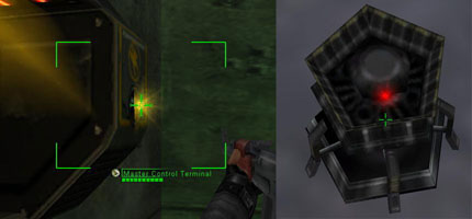
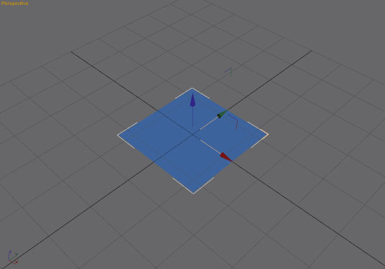
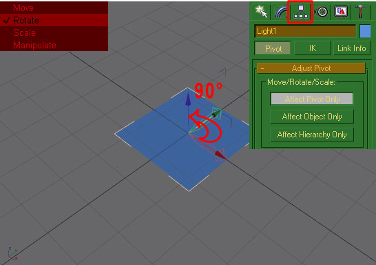
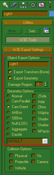
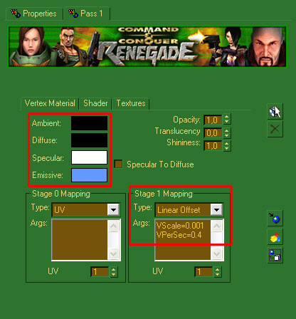
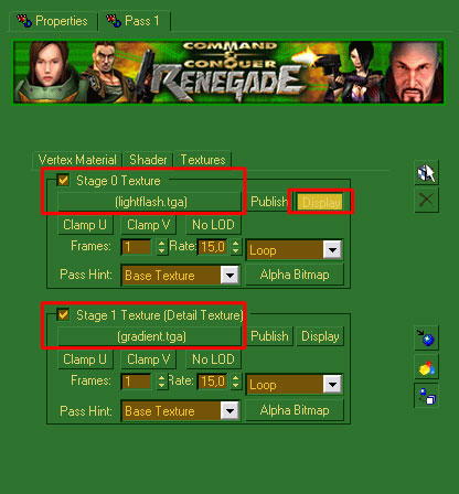
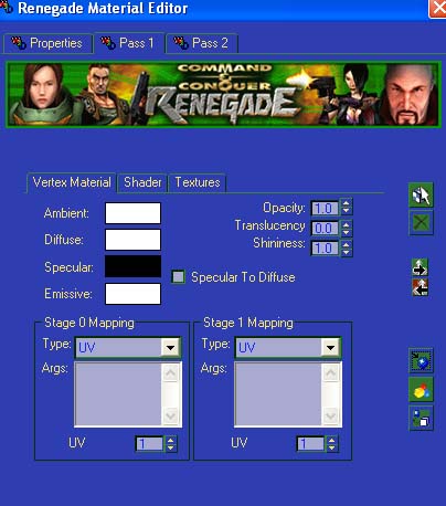
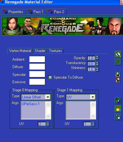
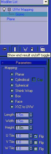
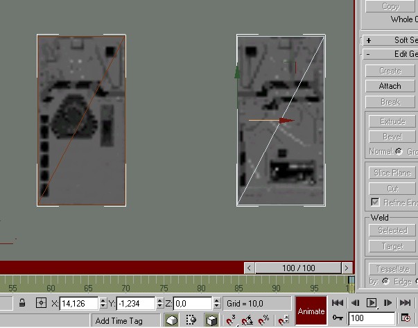
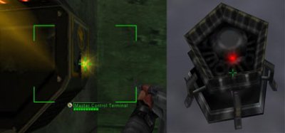
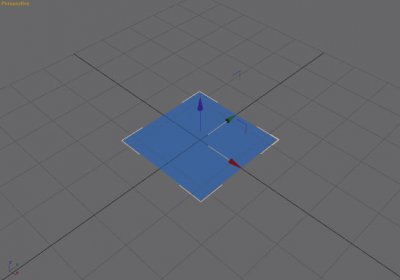
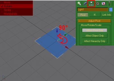
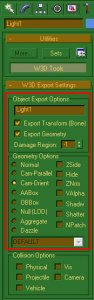
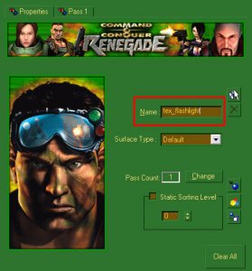
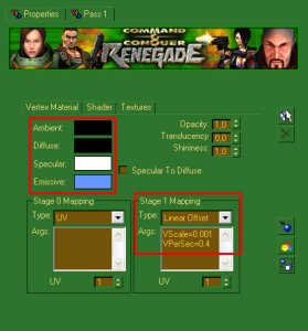
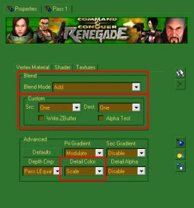
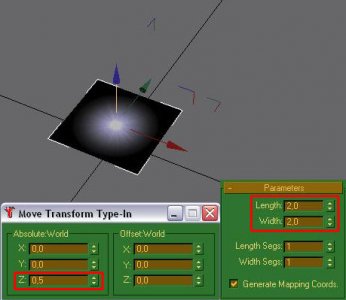
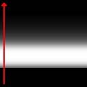
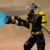
Author: Slave, Raptor-RSF Skill level: 3 In this tutorial you will learn how to create basic (flashing) lights in renx or 3dsmax. In the example above is showed the flashing light explained in this tutorial. It works the same as the basic lights, seen on the Ion Beacon and MCT's but with some additional settings. Step 1 Download the Tutorial files. Step 2 Open renx or 3dsmax and create a plane (size doesn't matter). Step 3 Rotate the Privot -90 degrees on its y-axe. Step 4 Modify the setting in the "W3D Export Settings" rollout as shown below. Step 5 Set up the texture in the "Renegade Material Editor". To edit the light color just click on the "Emissive" colorbar to modify it. Step 6 (optional) You may rescale the plane to 2x2 meter and lift it to 0,5 meters for ingame testing. Step 7 Export the file as a normal "Hierarchical Model". If you want to test your flashing light in the game, just save it to w_c4-p.W3D and place it into the renegade "Data" folder. Run Renegade and look at the Proximity C4 (landmine) while its on the ground. Warning: Renaming the file after export may result in errors and game crashes. Adjusting the lightflash - If you want the light to have a faster flash, just edit the "VPerSec=..." Argument. - If you want the light to have a different flash pattern, just edit the gradient texture. The flash pattern moves in the direction of the red arrow: Credits: - Slave (Knowledge of the flashing light and creator of the gmax file) - Raptor [RSF] (Writing this tutorial)


-
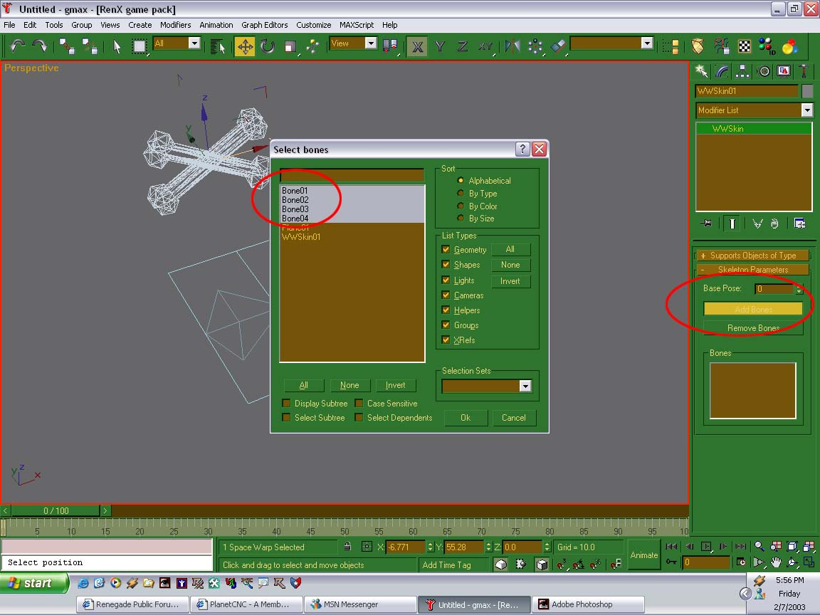
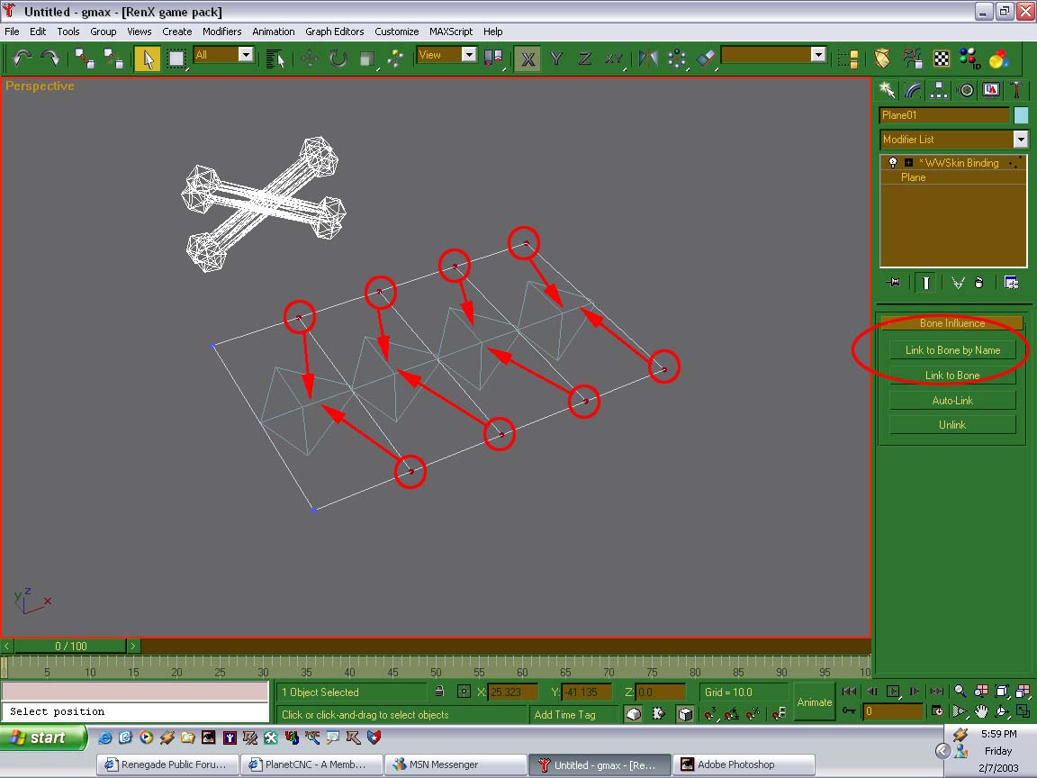
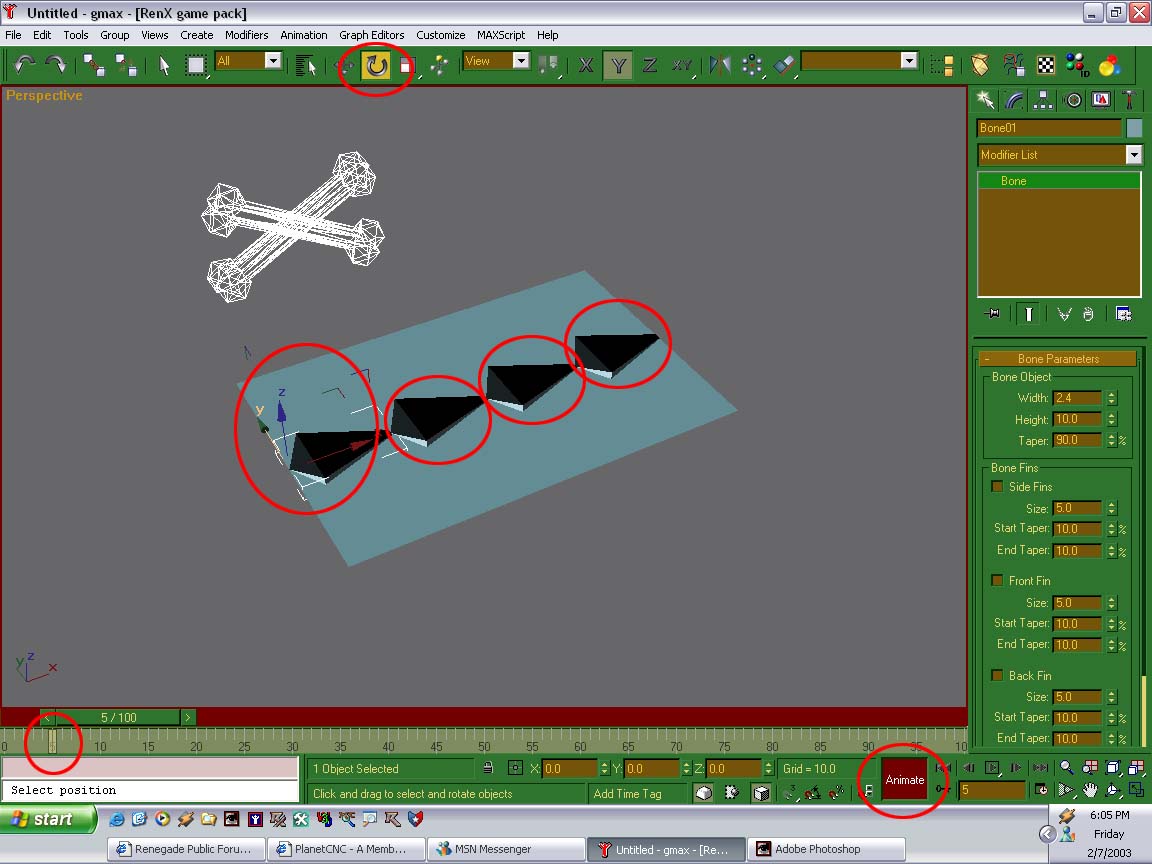
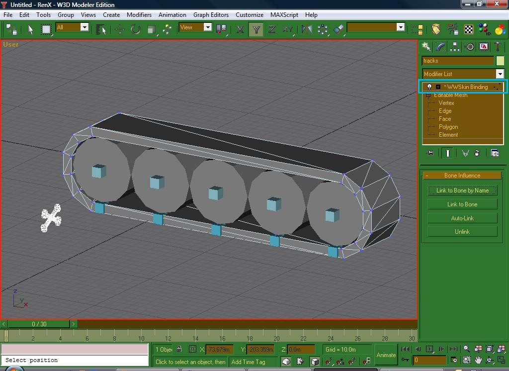
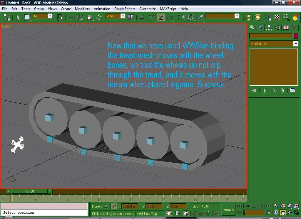
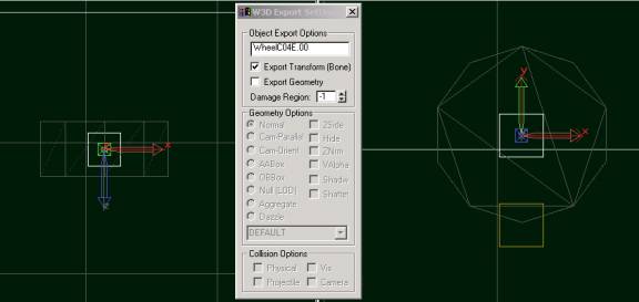
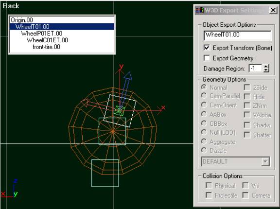
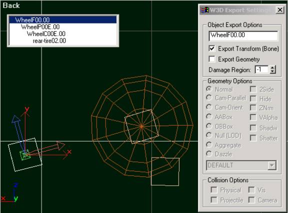
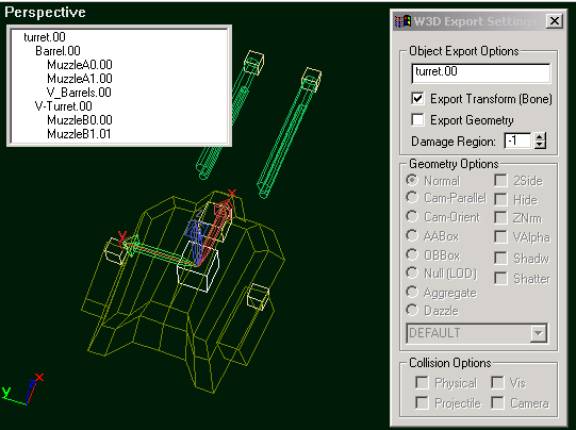
Author: moonsense715 Skill level: 3 This video tutorial will show you: How to rig a Tracked Vehicle in 3ds Max for W3D. This includes making the track texture animate. How to add it in LevelEdit and set up its physics. How to add the vehicle to the War Factory purchase list. Watch in HD!
-
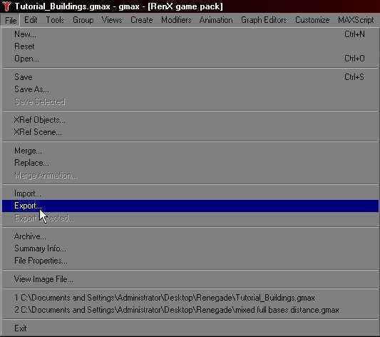
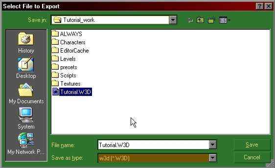
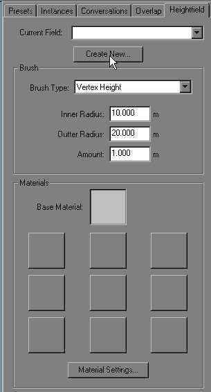
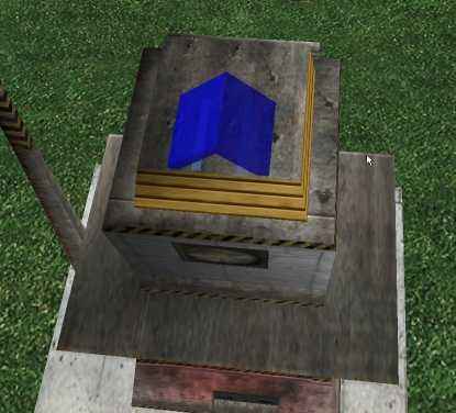
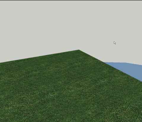
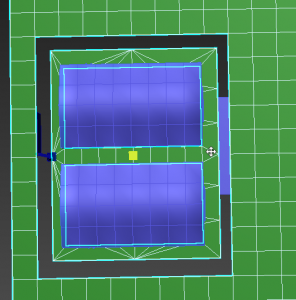
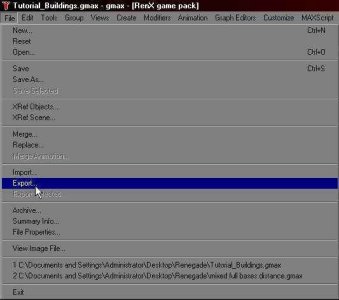
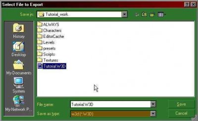
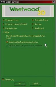
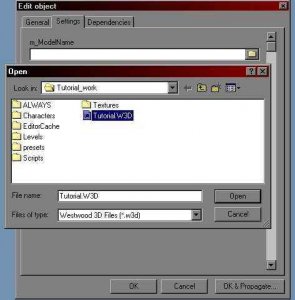
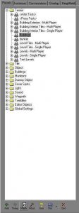
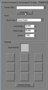
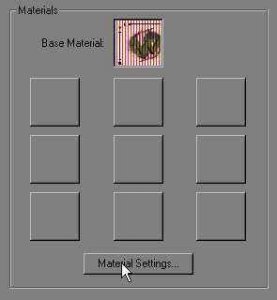
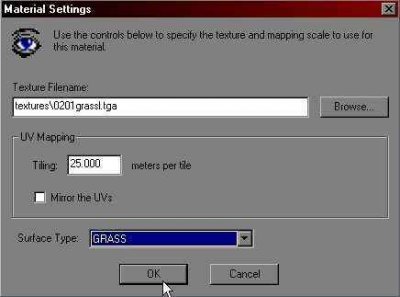
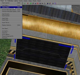
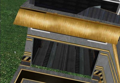
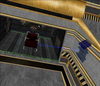
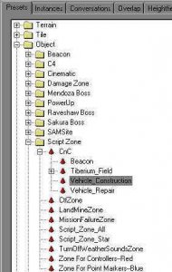
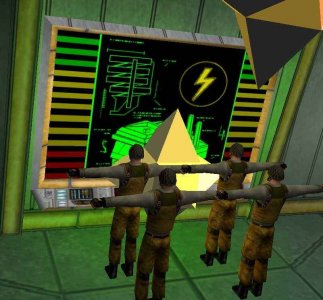
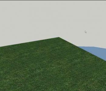
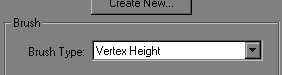
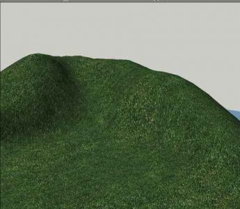
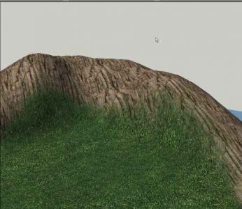
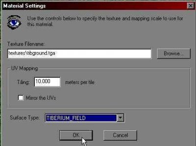
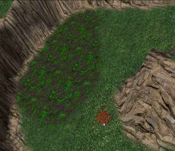
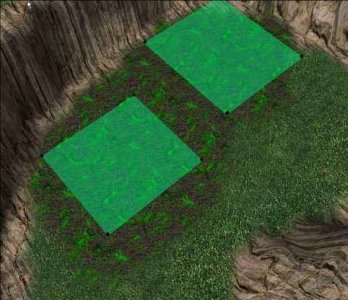
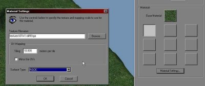
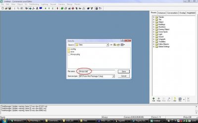
 Author: Oblivion165, moonsense715 Skill level: 3 This tutorial will guide you through the generic steps to make a typical C&C mode map with buildings work. It does not cover how to model a map in GMax-RenX/3ds Max but does give an insight into Heightfield as an alternate way to shape a map. Placing your buildings To get buildings on your map you first need to position them in GMax-RenX or 3ds Max. For that you need to download the buildings. Renegade Buildings Reborn Buildings BROKEN LINK Merge them onto your map (File -> Merge, select the buildings, add to scene). It should look something like this: Now position them where you wish and modify your terrain around them to match their exterior's shapes (almost all of the building interiors have their own floor so make sure you have no terrain under them!) Note: if you wish to make your terrain in LevelEdit's Heightfield, you only need to position your buildings and not create any terrain here. Then Export the file, just like this: Save your File: (in your mod Directory IE C:\Program Files\RenegadePublicTools\LevelEdit\Tutorial_work). Make sure it is .W3D filetype. Click Renegade Terrain and hit OK Adding your buildings in LevelEdit Start Level Edit, and click on the Preset "Terrain" and hit Temp. On the popup window's General tab, name your new preset (e.g. myterrain, mybuildings, etc). On the Settings tab, click the directory icon next to m_ModelName and select the W3D file you just exported. Leave m_LightFilename empty and hit OK. Select your new preset and hit Make Optional: Add a Heightfield map If you did NOT export a map along with the buildings, you have to create a heightfield level. Otherwise, skip this part. Switch to the Heightfield tab and click Create New: Set your dimensions (or keep them as default) and hit OK. Click Material Settings Select a tga format texture file from your mods's Level Edit folder and make the settings similar to this then hit OK: Now your new heightfield terrain should appear under your buildings like so: Optional: Working with Heightfield If you haven't created a Heightfield for your level (because you created your map in GMax-RenX/3ds Max), skip this part. Creating hills NOTE: save before making height fields, you can't undo them. Save often, because if a mountain goes into a building, you'll never get it level again. Pick a spot, anywhere you want a hill: Make sure your setting are like this (Heightfield tab): Click this button to affect the Heightfield: Now click and hold your mouse to create cliffs/mounds. Right-click to decrease the height. Adding extra textures Use this same technique to add other textures to maps (switch Brush Type to Texture Paint). Make sure you use an empty material box for each texture. Tiberium Field Just add this texture, set it to tiberium field (it will damage people walking into it) Making the buildings functional Every building needs its own, unique building controller to function properly. (Building controllers are under the Preset tab -> Buildings in different "folders", usually named bld_name or mp_name. Click on the appropriate one and hit Make to place it. These are not visible ingame, only in the editor.) This example will show how to set up the buildings in Renegade but most of them work the same way in other games too. Advanced Guard Tower Put the building controller on top like this: The Advanced Guard Tower controller is under generic buildings, make sure you use the one called "mp_GDI_Advanced_Guard_Tower" on it. Barracks Power Plant Refinery Refineries are setup different. Placing the controller alone is not enough. Select the controller and hit CTRL+P to add and position the Car Marker: Weapons Factory The GDI Weapons Factory has a door that blocks you from placing the Car Marker inside. To move that out of the way, click Edit -> Terrain Selectable (must be ticked) Click on the Weapons Factory door and then Unlock it: Hold CTRL + SHIFT and the up arrow to make it move up, just hold shift and the up arrow to make it go up slower. Select the WarFactory controller, Hit CTRL + P again to make the Car Creator, and place it in the middle of the war factory, make sure its centered on all side so its in the middle. Now make a Vehicle Construction Zone: This makes it so people will die, if they are in this zone while a Vehicle is created (but the vehicle needs it too to drive out from the bay on its own so don't skip placing it!). Strech it out by clicking on the black box in the corner (Shift-drag to stretch it upwards). Put the door back (hit Enter while it's selected to lock it again), and also make the terrain un-selectable, by unchecking it under Edit. Create Waypoints They are under waypaths, and use the Vehicle Only Waypath, Hit make and draw three points, hit esc to stop drawing them. make three paths just like this: then slide the three nodes a little more under the door, make it close to the car maker. Double click one of the nodes, NOT the whole strand, just one node, and select these options. Obelisk Place the controller to the very top tip of the Obelisk and then double click it. On the Position tab, make the Z coordinate 41 meters smaller so it will appear UNDER the building. Airstrip Make the airstrip look like this, use the same technique as on the gdi side. Make sure the car maker is facing the way the arrow is. Also make the top 3 nodes closer to the carmaker than shown in my pic. Tiberium fields Now you need to place Tiberium Zones: Make one for GDI, and one for Nod. A tiberium field should be equal distance from each base, or make each base have its own. Make a waypoint from one of the paths coming out of the Weapons Factory and Airstrip. Make the waypath go to the tiberium field. (its only one way, you dont have to draw it there and back, only there). Also give this waypath the same settings as before, by double clicking one of the nodes. Now make a waypath from the Tiberium Refinery to the field. Again, only one way, you dont have to draw it back. And also give this path the same settings as before. Spawners and PTs TS: Reborn has the PTs and Spawners placed already from the imported w3d building files. So if you are making a Reborn map, you can skip this step. Go into a building, and find a pt. you have to do this for every Pt and Every Spawner, if you are setting up a Renegade map. Find the PT object on the preset list and hit Make: Position it over the PT model: Now place some Spawners to where the players will start (next to PTs): Position and rotate them so they face the PT object. This will make players face the PT immediately after they spawn. Now redo this step for every single PT in the level Generate Pathfind for AI Harvesters If you don't already have one, place a Human Pathfind Generator somewhere (preferably close to Refinery, you can also place one at both refineries) Now click Pathfinding -> Generate Sectors. This can take a long time depending on the map size, sit back or take a break until it finishes. Thats it, export your map and have fun!


-
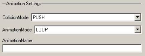
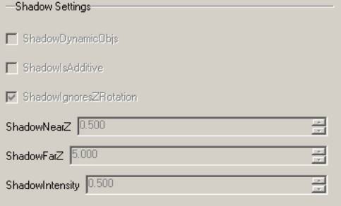
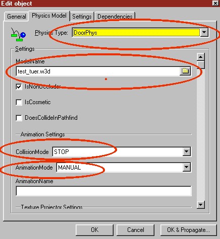
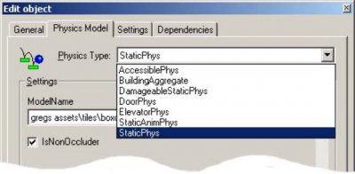
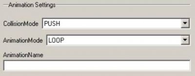
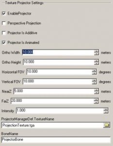
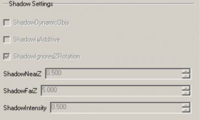
Author: Westwood Studios Skill level: 3 By Greg Hjelstrom Introduction A level for Renegade is composed of static and dynamic objects. This document will give you a brief overview of the types of static objects you can create. Static objects never move and cannot be created or destroyed in game. That being said, you can do a lot of things with animated static objects (including hiding or un-hiding the object, achieving the effect of creation or destruction). In the Renegade level editor, there are two categories of static objects: Terrain and Tiles. These two types are handled significantly differently. Terrain A terrain for Renegade is treated as a collection of individual meshes. A terrain cannot be animated or changed in any way. The bulk of the geometry for any given level is in the form of one or more terrains. Terrains should always be exported with the Renegade Terrain option in the Tiles Tiles are static objects that can animate in various ways. Doors, elevators, damageable objects, and building aggregates are all examples of tiles. The physics model you select when you set the tile up in the editor defines the logic that controls how a tile animates. Below is a list of the physics models available to tiles: StaticPhys An object that uses the StaticPhys physics model is just a static object in the level. This is the simplest type of static object and cannot animate. The only two parameters are the model name and a checkbox indicating whether this object is an occluder. StaticAnimPhys This is a simple animating object. This can be used to make trees that sway, radar dishes that spin, etc. All of the other physics models in this document are derived from StaticAnimPhys and have all of its parameters. Animation Settings: Collision Mode: The most powerful feature of animated tiles is the ability to animate the physically collideable meshes in your model. You can select from several collision modes: none, stop, push, and kill. Probably the most useful of these is the push mode. The push mode will cause the physically collideable meshes in your tile to push the dynamic objects in the game. One limitation must be kept in mind when you use this mode however you may only use translation on meshes that are animating with collision mode push. Elevators (called lifts in other games) simply use the push collision mode on their mesh to move characters and vehicles around. Animation Mode: There are three animation modes: loop, target, and manual. Loop is the most common mode and simply causes the object to play its animation over and over. Target and manual are used when there is other code controlling the animation of this object. Animation Name: Normally, a StaticAnim object will use the animation built into its w3d file (just use the Hierarchical Animated Model option in the exporter). However, if you want to play a different animation on the object, you can specify that animation here. Typically it will be in the fully qualified form: .. For example, if you export an object named MyTree. Then you create a separate animation called WaveAnim, then the full name of the animation will be MyTree.WaveAnim. This parameter is often needed if your tile is an aggregate model created in the w3d viewer by attaching emitters to another model. Texture Projector Settings Enable Projector - Does this tile have a texture projector. Perspective Projection - Should the texture projection be perspective (default is orthographic) Projector Is Additive - should the texture projection be rendered additive. The default is to render multiplicative which is useful for creating shadows; additive can be used to create spotlights. Projector Is Animated - indicates to the engine that the projector is moving and should be re-checked for culling each frame Ortho Width - width of the orthographic projection (used when Perspective Projection is false) Ortho Height - height of the orthographic projection Horizontal FOV - Field of view of the perspective projection. Vertical FOV - Field of view of the perspective projection Near Z - near z clipping plane for the projector, only used for rough culling, not clipping Far Z - far z clipping plane for the projector Intensity - The darkness of the projector (or brightness if it is additive) Texture Name - name of the tga file to project Bone Name - name of the bone to attach the projector to. Shadow Settings Tiles may have a static shadow projector that is automatically generated at level load time. An example of this feature is the trees in various levels in Renegade. When dynamic objects move into the shadow volume of the tree, the tree shadow is projected onto them. The engine will share the shadow projection texture between multiple instances of an object whenever possible so you can have lots of shadow projectors in your level. Unfortunately, these projectors do not currently project onto static geometry because we used light-mapping for the static shadows. Below is a screenshot of the shadow parameters available to static animated objects: ShadowDynamicObjs - this checkbox enables or disabled the entire shadow feature. ShadowIsAdditive - (may be obsolete) can be used to make stained glass window types of effects where the shadow is an additive effect rather than a black silhouette effect. ShadowIgnoresZRotation - allow instances of this tile to share the shadow texture even when they are rotated. This works well for trees where you cant really tell the difference in the shadow anyway. ShadowNearZ - near z clipping plane of the shadow ShadowFarZ - far z clipping plane of the shadow ShadowIntensity - how dark (or bright if its additive) the shadow is.
-
 Author: Jonwil Skill level: 3 I have discovered how the "compute vertex solve" option in leveledit works and here are my findings: 1. The "Enable Filtering" and "Solve Selected Objects Only" checkboxes do nothing (probably why they are disabled) 2. The weather, sky and background settings under "Edit-Background Settings" in leveledit have no effect on the vertex solve what so ever. 3. The sunlight and ambient light settings under "lighting" in leveledit do affect the vertex solve. The ambient light in particular can be tweaked to give all the things in your level, dynamic objects/spawned items/etc included, a nice green or blue or red or whatever tint. 4. If the mesh has vertex colors set, they will be used. If the mesh has a material, it will use the diffuse and ambient settings from that material. 5. If the "occlusion enabled" checkbox is selected, some math happens that involves the vertex being lit, the position of the light currently being processed and possibly also the Far Attenuation settings. The results of this math (which I dont understand) are used to cast a ray into the scene. If the ray hits something, the vertex is not lit using that light. Seems to be to stop lights from lighting vertexes that they can't actually cast light onto because of obstructions in the way. This only checks for terrain or tiles that are in the way, not objects or anything else. 6. With the latest versions of scripts (dating back to somewhere in 2011 I think) you can now put Prelit=true into the "mesh user text" of a mesh (not sure exactly what that is in Max and I dont have Max running right now to check) to cause the lightmap code to not calculate shadows on that mesh. Note that the mesh will still be affected by ambient and diffuse(sun) lights. 7. With the latest versions of scripts (dating back to somewhere in 2011 I think) it will now correctly light meshes that have no vertex colors and that have an opacity of less than 1 (or 100% or whatever it is). This includes the glass for the renegade Hand of Nod and renegade Nod Airstrip, meaning you no longer need to hide those meshes before you light solve. 8. With the latest versions of scripts (dating back to somewhere in 2011 I think) it will now not apply lightmap data to mesh pieces that have bump mapping (this includes water on various stock Renegade levels and others, meaning you no longer need to hide those objects before you light solve). This fix is handled at load time meaning it works on all maps without even needing to re-run vertex solve or do anything special.
 -
Author: Jonwil, Generalcamo Skill level: 3 You will want to download the sidebar textures for this tutorial. Now that scripts 4.1 allows you to use the sidebar stand-alone in a Renegade map or standalone mod, its time to write a tutorial for how its done. The first thing you need to create are textures for the sidebar. Included in the sidebar.zip file are some example textures from Tiberian Sun: Reborn as well as a source Photoshop file provided by Chronojam to show how it all fits together. You need to create a top half texture, bottom half texture and up and down arrow textures. They can be the same for both teams or different for each team. Then, you need to create an ini file. If your map is named C&C_MyMap, the ini file should be named C&C_MyMap_tt.ini. Alternatively, if you are creating a standalone mod, the ini file should only be named tt.ini. In this file put something like this [General] AlternateSelectEnabled=false NewUnpurchaseableLogic=false VehicleBuildingDisable=false GDIUpArrowTexture=gdisidebarup.tga GDIDownArrowTexture=gdisidebardown.tga GDIBackgroundTexture1=gdisidebar1.tga GDIBackgroundTexture2=gdisidebar2.tga NODUpArrowTexture=nodsidebarup.tga NODDownArrowTexture=nodsidebardown.tga NODBackgroundTexture1=nodsidebar1.tga NODBackgroundTexture2=nodsidebar2.tga sidebar=true Obviously the names of the textures should match the names you gave them when you created them. You can also optionally add the following if you want sounds to play when sidebar items are purchased: sidebarSoundsEnabled=true sidebarRefillSound=xyz sidebarInfantrySound=xyz sidebarVehicleSound=xyz Or for team specific sounds: SidebarInfantrySoundNod=xyz SidebarInfantrySoundGDI=xyz SidebarVehicleSoundNod=xyz SidebarVehicleSoundGDI=xyz The sounds need to be 2D sound presets created in LE. (obviously replace xyz with the name of the sound to use). The sounds are played whenever something is purchased (i.e. double click etc) Note that the sidebar does not display any text on top of the icons except for the cost so you will need to either rely just on the pictures or you will need to add text to your icons. Also note that all players using your map will require scripts 4.1 (as will the server) in order for this to work. Also, the sidebar does not allow you to purchase beacons (unlike the PTs) so if you want beacons to be purchasable, you will have to add separate terminals to let you do that (there are plenty of scripts to make that happen) If you wish to use the new tech level features of the sidebar, continue reading. First, in the C&C_MyMap_tt.ini file (or whatever), put this line at the end after the others NewTechLevel=true Then in leveledit, go to Global Settings then Purchase Settings. For each of Character Classes (GDI), Character Classes (Nod), Character Classes (Secret GDI), Character Classes (Secret Nod), Vehicles (GDI), Vehicles (Nod), Vehicles (Secret GDI) and Vehicles (Secret Nod), create a temp preset copy (or if you already have one, edit it). What you need to change is the Factory Building Type for each entry. For soldiers, set it to Soldier Factory. For vehicles, set it to Vehicle Factory. If you are using my helipad tutorial (to be posted shortly) set helicopters/air units to Helipad. If there are units you don't want on the sidebar (e.g. the secret hidden extra vehicles), set their object to none. The usual enable/disable for extras (EXTRAS console command etc) will not work with the sidebar. All of the hidden extras will be displayed be default otherwise. That should be all you need to do, no extra scripts are required, the engine logic behind NewTechLevel=true will do all the work of making the items vanish from the sidebar when the relevant building is destroyed. This should be all you need to know in order to use the sidebar in your map or mod. If you have any questions, post here (or talk to me on IRC/IM) and I will do my best to answer them.
-
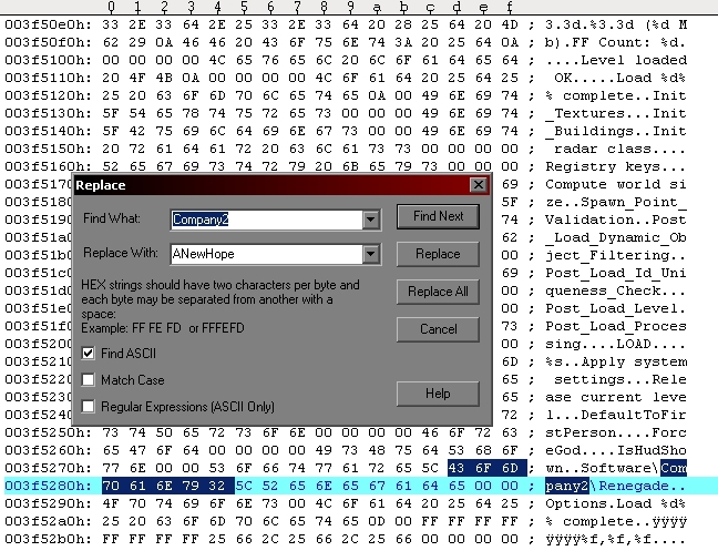
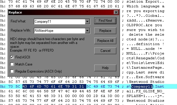
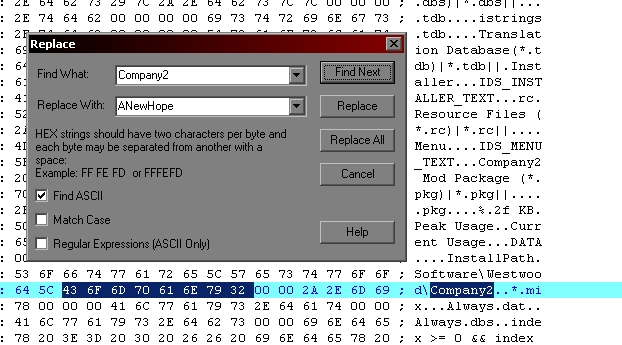
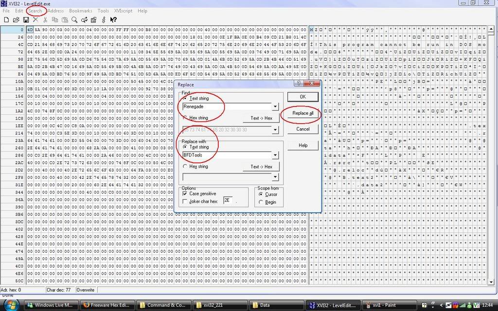
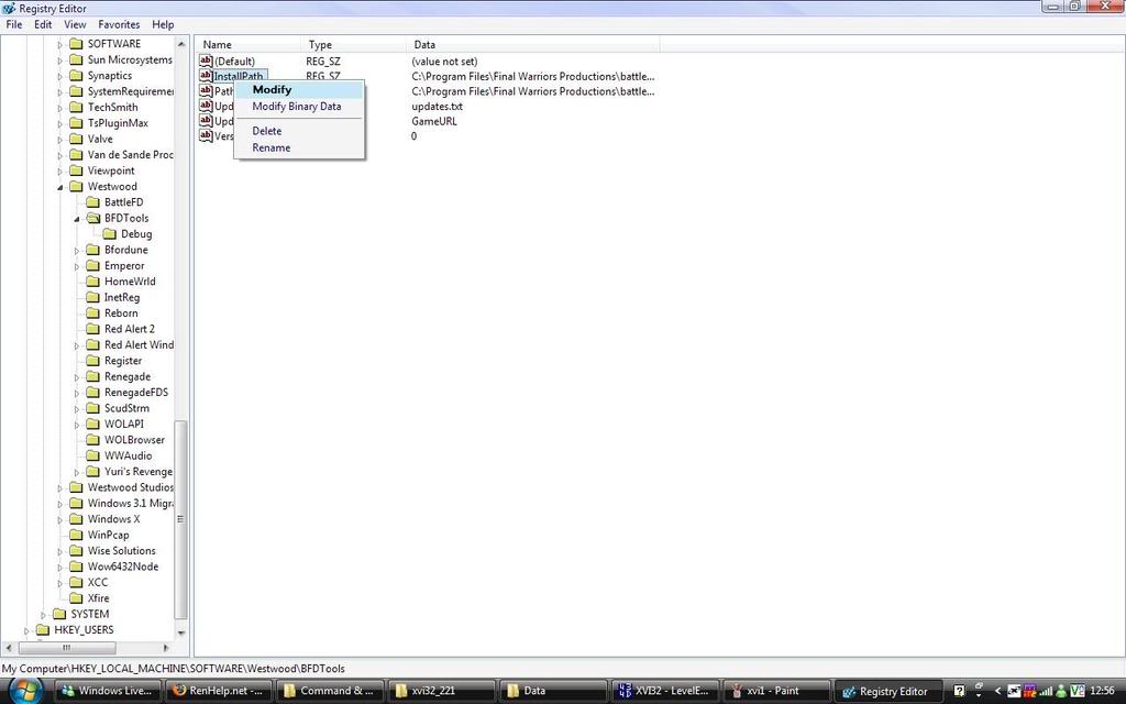
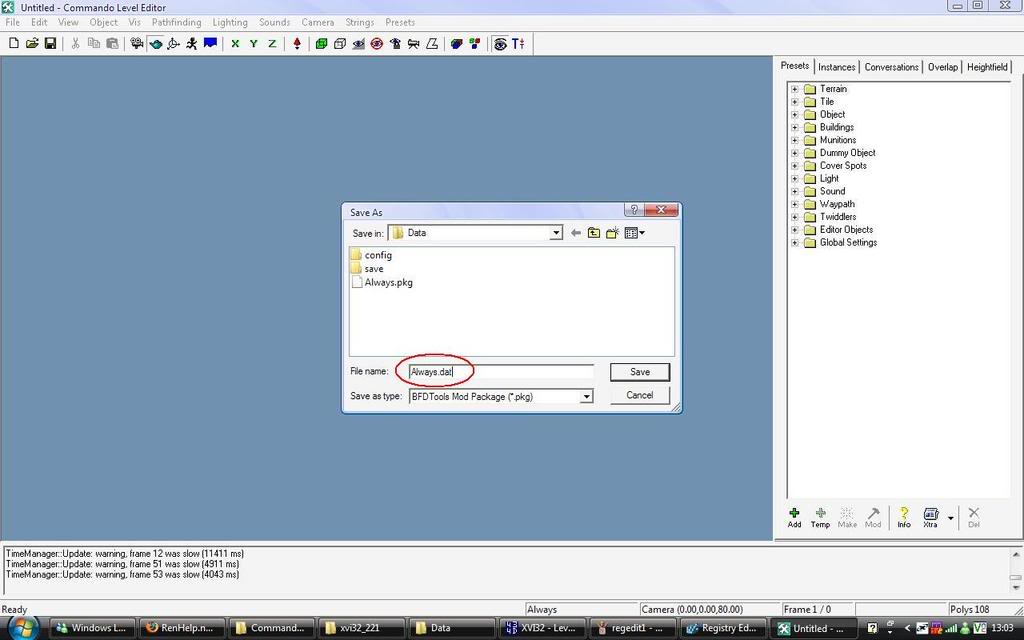
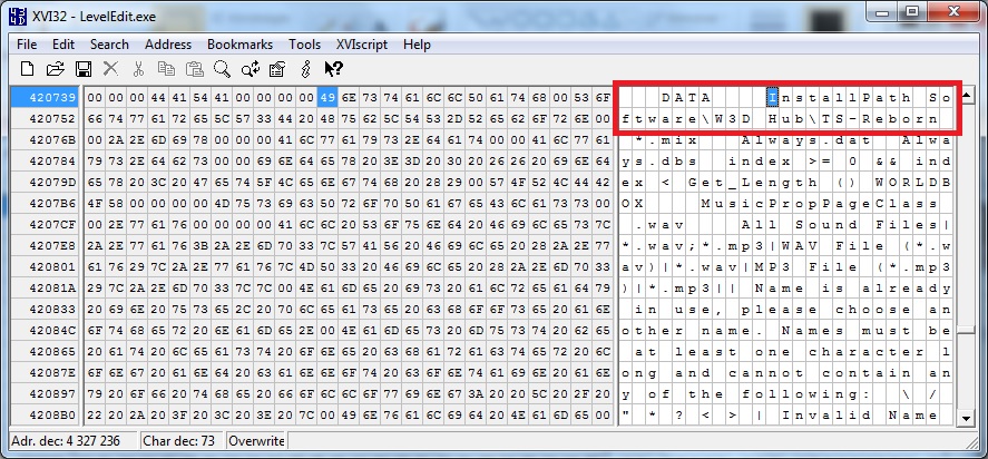
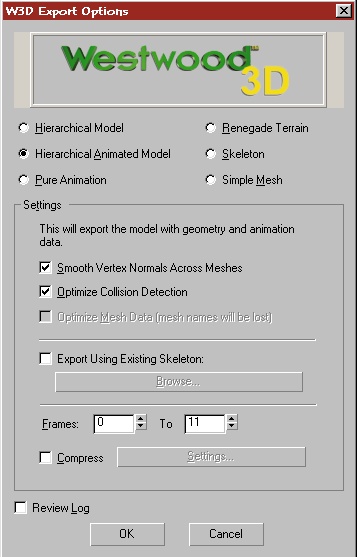
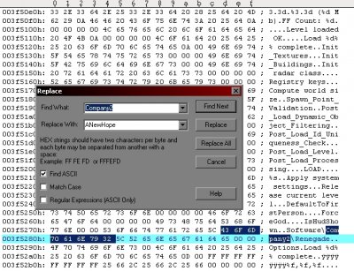
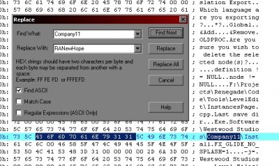
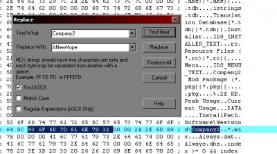
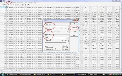
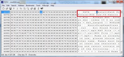
Author: moonsense715, Oblivion165, cnc95fan Skill level: 3 This tutorial will show you how you can create your own custom, standalone W3D game and a Level Editor tied to it. 1. The game Before you can make your game and its own editor, I highly recommend basing it off of something. So firstly, make sure you have a W3D game downloaded (e.g. using the launcher). Make a copy of the game's entire folder, where game.exe is sitting. Now you have a duplicate of your reference game. Find the paths.ini file in your copied game's Data folder. If there is none, either extract it from always.dat (using Xcc Mixer or RenegadeEx), or create a new file, with the following content: [paths] RegBase=W3D Hub RegClient=games\tsr-release RegFDS=games\tsr-release-server FileBase=W3D Hub FileClient=games\tsr-release FileFDS=games\tsr-release-server UseRenFolder=false RegBase/FileBase is the folder's name in your Documents folder (e.g. the developer or company name), and RegClient/FileClient is the subfolder with your game's name.Change all the folder names to match your game. Then save it as paths.ini. If you go ingame and hit Print Screen to create a screenshot, it should now be saved under \Your documents\Your specified subfolder\Screenshots folder. Your standalone game is done, but of course you will want to fill it with your own content. And for that you will need your custom Level Editor. 2. The editor If you do not have it yet, download the editor that is designed for your reference game from here. Otherwise, copy your LevelEdit folder. At the moment, your copied editor is tied to the reference game. You need to hex edit your LE to have its registry key point to your new game. Download the HEX editor XVI32 and open your LevelEdit.exe with it. Now search for InstallPath in non case-sensitive mode. The Reborn Editor for example, has it's reg path under W3D Hub\TS-Reborn. You need to REPLACE (CTRL + R or Search -> Replace) TS-Reborn (or whatever is there) with your own game tools' name that you choose. For example you can use MyGame-LE. Make sure this name is max 11 characters long. Don't forget to replace W3D Hub or whatever is before \your-game-name, with your own studio name. Save the edited LevelEdit.exe, your job here is complete. Now just drag and drop LevelEdit.exe onto leveledit_path.exe (don't have it? Get it from here), choose your game's folder where game.exe is sitting and boom! You have your Editor set up! For older W3D games where paths.ini does not exist or work at all, the tutorial for how to make your custom game and editor is below.
-
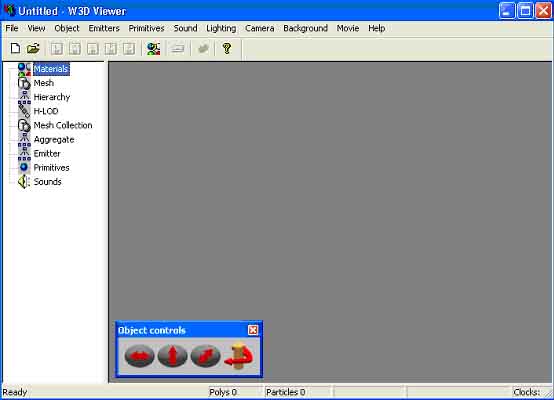
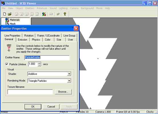
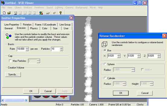
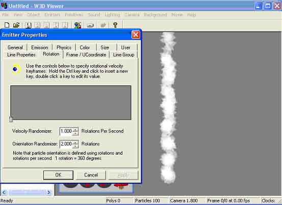
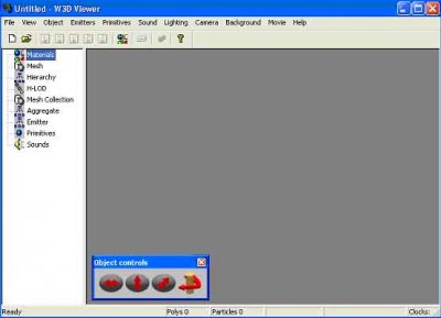
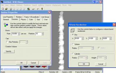
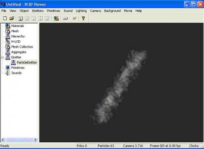
Author: Genocide Skill level: 3 Emitters serve purposes such as the smoke trail for the Rocket Launcher and Tiberium Dust. Creating a successful emitter is easier than you would of think, all you need is the Renegade Mod Tools which if you dont have you can get here: Renegade Public Tools After you have got that, browse for the mod folder, which generally is: C:\Program Files\RenegadePublicTools\W3dView, after that you will see W3dview.exe, open that and you should see the following: After the program is open, select the Emitters tab located at the top menu then choose, Create Emitter, when that happens the following window will open where you will edit all your settings: Here you shall name you emitter anything you wish, I suggest if you are making a smoke Emitter you leave the Particle Lifetime to 1.000 Secs, for future reference, the longer the Lifetime the longer the Particle Trail. I have changed the Rendering Mode To: Quad Particles Now we are going to add a texture to the emitter, you can do so by going to browse and search for a .tga file extension file. (If you have a texture and want to convert it to a .tga file then download advanced paint programs such as Jasc Paintshop Pro, and Adobe Photoshop) After Selecting, the best shader for a light Smokey texture would be Screen, after selecting that the texture we need to move to the Emission Tab where we will change the Density of the Emitter this is what I have done by editing the Particles, Rate And Creation Volume : Now, Notice the more dense the emitter has got, now time to move to the Rotation tab, I have skipped a few tabs because they will not necessarily be needed when creating a smoke Emitter, here I have edited rotation to make the emitter look more realistic: Now we are finished with the Very Basics of creating an emitter , I suggest playing around with this program to find out just what amazing emitters you can make, even ones that have sound attached to them! , I hope I have entered you well into the world of emitter creation, after playing around some more here is my finalised smoke emitter : Thanks for reading my tutorial and I hope that you become a great emitter creator, Genocide.


-
Author: General Havoc, Havoc 89 Skill level: 3 In this tutorial you will learn the basics on how to make rippling effect. This tutorial can be used to make rippling flags, water, etc... Step 1 Create a plane with at least 4 or more "Width Segs". Step 2 Press F3 (Wire Frame Mode). Go to the create tab and select "systems" (looks like two gears) then click on "Bones". Step 3 Select the "Bone" button and click once on each Width Seg. Step 4 Click "Create Renegade Skin" on the top right and make one. Step 5 Click on the Renegade Skin. Click on "Add Bones" in modifier tab and add the bones that you have made. Step 6 Click on "Bind to Spacewarp" button on the top corner beside "Create Renegade Skin" button. Press and hold the plane after clicking on bind to Spacewarp button, move you mouse over to the renegade skin and release the button. You should see the renegade skin go darker for 1 second and then go back to being white. Step 7 Click on the plane and select 2 vertices and link them to their bones. The circle bones represents which 2 vertices are selected. The arrow represents which vertices are linked to which bone. You should hear a sound when you have successfully linked them. Step 8 Press the "Animate" button (bottom of the screen). Select the rotate button on the top. Click on one of the bones and then start making a rippling effect animation. Note, you should see the plane moving as well. Step 9 After you have done with animation select all the bones and go to W3D options and uncheck "Export Geometry". This hides the bones so they don`t appear in game. Then export as a an hierarchical Animated model Step 10 Press "Add" in level edit under Objects > Vehicles > Mounted. Name it and then under :Physics Model" tab. Change Physics Type to DecorationPhys. Then use your object that you exported. Step 11 You will need the right settings. Under the "Settings" tab change health to -1 and Health Max to -1. Then Scroll down until you see something called "NonTargetable", check it off and right underneath it, you will see an animation bar which says "Animation" Enter your Flags Animation name. To find out your animation name run W3D Viewer and load your object, then click on the "+" sigh on Hierarchy. You should then see your object name with a "+" sigh behind it. Click the "+" sigh, then you should see your objects animation name. Example: "FLAG.FLAG" this is what my animation name is for my flag. Step 12 Click the "Make" Button in level edit and place your flag anywhere you want. Finished Enjoy your first rippling flag! BTW: You can also use this for other things, not just flags. You can also do this with water. Congratulations you have passed Basic Rippling Effects Tutorial. Credits This tutorial was originally written by Havoc 89. The tutorial was converted to HTML format and edited by General Havoc. I`d like to thank Havoc 89 for originally writing this tutorial and I hope it is now more useful to people in a better format. Also many thanks to the many people who help on the Westwood Mod Forums. Finally of course Westwood Studios for the excellent series of C&C Games. Let Westwood Live on!
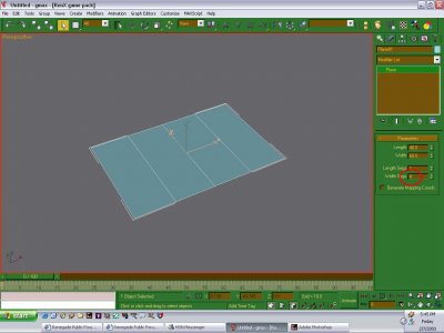
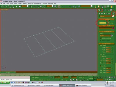

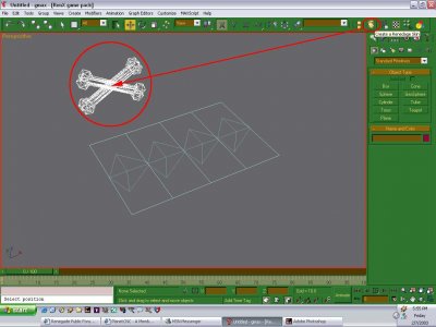

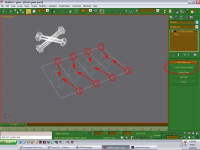


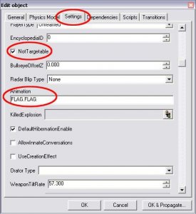
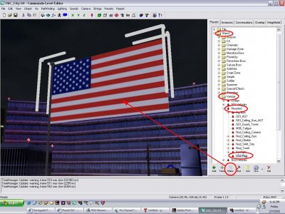
-
Author: Läubi Skill level: 3 First of all, some things you should keep in mind about elevators: an elevator might cause problems if there are alot elevators, or if people try to use the same elevator at the same time with a slow connection (56k for example) people might fall "through" your elevator and popup at the top after some seconds elevators can NOT transport vehicles! You should always take care that the Transition Zones (explained in the tutorial later) are not reachable for vehicles because the wil get STUCK in them! elevators often cause problems with beacons, if you try to deplay them ON the elevator plattform 1. First Step is of course, create your elevator. This is myone. Ok its not very nice but thats a 2 min one Basicly an elevator has a platform (in this image the red parts), and a door (the blue parts). Of course an elevator can also have other parts in the deep of complexy you want but for this tutorial this is the best choice. Always create your elevator in the center of RenX/Gmax.To get an ide of the size of an elevator, the Single Player ones have an aprocxiamte size of L: 6m, W: 6m, H: 12m You can create a box with these settings to get an idea if your elevator has the right size: (my elevator is a bit too big as you can see, but the size is your choice, you just get a general idea about the size with this method) 2. Because the Rengade-Engine don`t like textured objects that are moving we now create some "cages" that later will be invisible, but responsible for the collision parts. These are basicly just meshes without a texture that covers that elements, that later collide with players. Activate the W3D hide and collision Settings: Vehicle, Camera, Projektile, for the textured Meshes don`t activate any Collision Settings. 3. Now it is time for the animation, an elevator has 3 Animation stages: Stage 1: (Baseframe) Move all your parts of the elevator so it is on the Top-Part, with the door open for enter at the Top: As you can see I just moved the whoe plattform up, and lowered the ring so if the player can enter the elevator at the top. Stage 2: (On the move) Now klick the animate Button, Goto Frame 1 and move your door so it is closed (you can use more than one frame if needed, just note this framae somewhere) Now on the trackbar goto frame 10, and move the elevator down, so it is on the botom with an closed door (same comment as before for the cloe door thing): The best is you note this frame on a paper or something, because you`ll need this later. Stage 3: (Final Animation) Now just make an animation when the door moves down, so you can leave the elevator. My one ends on frame 11, because only one frame is used for open the door in my example, of course you can use as many as you need: Now you`r finihed with this, deactivate the anim Button and feel good that the work is nearly done. 4. Export the elevator to your Modpacket: Export it as HirachyAnimated Model and from Frame 0 to the last frame (in my example frame 11): 5. Open the Commando (Leveleditor), browse to Tiles and press the Add Button Now enter a name, e.g. my_elevator, and switch to the Settings Tab Change the type to ElevatorPhys, Select your W3D and change Collision Mode to STOP, Animation Mode to Manual. Scroll a bit down and set DoorClosedTop to the frame when the door at the top is closed (that is frame 1 in my example), DoorOpeningBottom to the frame where the elevator is at the bottom with open door (Thats frame 11 in my case) ElevatorStartTop that is in nearly all cases frame 0 ElevatorStoppedBottom this is the frame where the elevator is at the bottom with closed door (Frame 10 in my case) Now cahnge the CloseDelay to the Time the elvator should need to go up/down and press OK and your nearly ready for test your elevator. 6. Ok, now its time to tell the elevator where people will wait to enter: Select your elevator again and press Mod, goto the Zones Tab. You see 4 Zones: LowerCallZone: Defines the zone where the Character has to stay in to call the elevator to come to the bottom LowerInsideZone: When you are inside this zone the elvator starts to move Up UpperCallZone: Same as LowerCallZone but for the top UpperInsideZone: Same as LowerInsideZone but for the top When you doubleclick you can adjust the zones t the size / position you need. First / Lastframe switsche between the start and end frame so you easy can adjust the zones. Adjust now all zones like it is explained above. Here are mine: LowerCallZone LowerInsideZone UpperCallZone UpperInsideZone Now press OK and your done with the setup. 7. Load your Level and select your elevator then press Add and it will apear on the map: Export your Map and test the elevator 8. Congratulation! You can now go up and down with your elevator as long as you want.
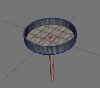

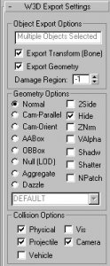
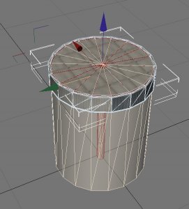
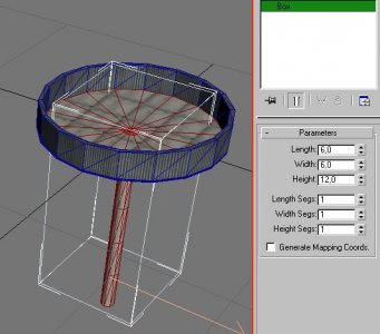

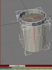
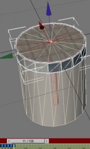

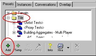
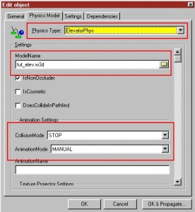
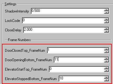
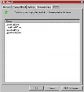
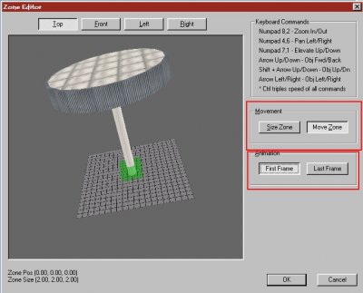
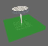

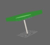
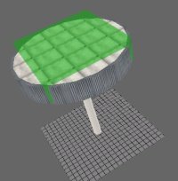
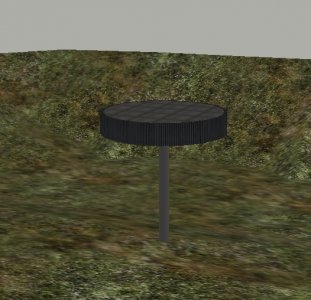


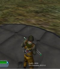
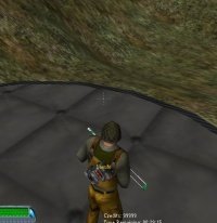
-
Author: Stonerook Skill level: 3 Project: Duplicate the moving computer screens as seen in MP/SP Renegade buildings computer screens using vertex settings only. Materials: atr_blips.tga atr_scem01.tga hnd_wrksta.w3d (for reference) All found in C&C Renegade's always.dat Programs: RenX W3D Viewer Commando C&C Renegade (LAN Mode Mod Package) This tutorial assumes that you have working knowledge of the programs needed. This means you know how to use them make levels in Commando setup a single player LAN game. Rev. 1.0 02/08/2003 This is the moving computer screen in the Hand of Nod - hnd_wrksta.w3d. Take a look at it the color bars move up and down and right to left. The pattern of the background will take on the colors as the front color texture flows across it. Its a simple mesh plane with two applications of texture (2 pass) and the moving texture is simply a vertex setting. The trick is you have to apply two (2) UVWs to the mesh one per texture. You also need to rotate the second one a certain way to get the moving color bar effect. If you just apply the vertex settings (as per wdump) you will not get the same effect So here is how Westwood did it. Step One In Renx make a mesh 2m,2m segments 1,1 use the front view to make it in. Name it Cpu_test Step Two With the mesh selected Hit the m key. Set your Pass Count to two (2) Name the Material cpu_scrn Select the Pass 1 tab for the next step. Step Three Set this texture to atr_scem01.tga (this is the background texture) Next hit the Shader tab (for Pass 1) Step Four Set your Blend to Opaque as seen above. Next hit the Vertex Material tab (for Pass 1) Step Five Set your VM to the following: (R,G,B) Ambient 255,255,255 Diffuse 255,255,255 Specular 0,0,0 (you could set it to 0,255,0 if you want a glowing neon) Emissive 255,255,255 Opacity 1.0 Translucency 0.0 Shininess 1.0 Your UV is one (1) - for this texture Step Six Select Pass 2 Select atr_blips.tga for this texture. Hit Display on this texture (this is the moving one) Select the Shader tab for the next step. Step Seven Set your Blend Mode to Multiply the rest of the settings should be as shown above. Step Eight Set your all your Vertex Material colors to 255,255,255 down. And your Opacity/Translucency/Shininess are default. Set your Stage 0 Mapping to type Linear Offset Your args will be UPerSec=.1 (caps are important) Set your UV to two (2) Assign the material to the mesh then x out of this dialog. Step Nine Now assign a UVW map modifier and then on the Channel/Map Channel roll down select 2. This allows us just to play with the pass two texture since we put it to UVW 2 under the vertex settings. Now we have to fix the texture to show correctly. Step Ten First flip the map U tile check the Flip box. (this is so the map will display correctly. Second make the UVW map a bit larger than the mesh you can play with the settings to get different settings I made mine 2.5m length and 2.5m width. (different sizes different effects) Then use the use the UVW mapping gizmo and the select and rotate gizmo to spin the UVW map 90° on the Z axis. (Y on the UVW map) So the UVW map should look like this: Now with that done unclick the UVW map option right click on the mesh and change it to a editable mesh this will collapse the mod stack and lock in your settings. (Don't convert it to editable mesh if you want to change the settings on the UVW modifier later.) Now export the mesh as terrain and name it cpu_screen.w3d Open the file with W3D viewer and you should see the a moving computer screen just like the Westwood ones. This is something I whipped up I changed the background texture So by changing the background picture adding some colors from the atr_blips you can make your own custom cpu screens. Photoshop is invaluable in this you can use filters to make the "negative " of your line are to make interesting displays. (I use antimatter) Any questions or comments please email me stonerook1@hotmail.com. Info for this tutorial was taken from the supplied Westwood© meshes and materials. The rest was using the knowledge given by doing the Gmax© tutorials. And the rest a lot of Jolt© soda. If you find this useful please let me know. StoneRook out "patent pending"©
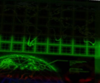
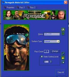
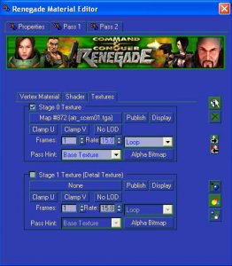
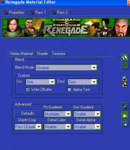
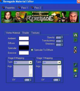
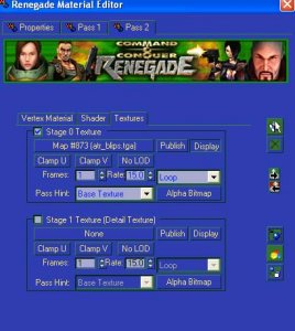
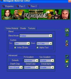

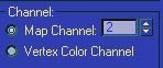

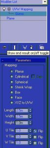

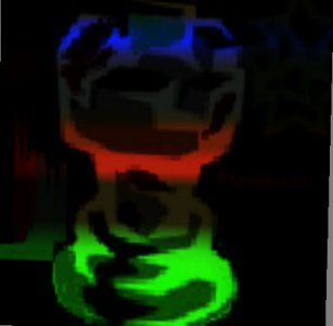
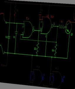
-
Author: Läubi Skill level: 3 1. Create your door in GMAX/3ds Max (It may looks a bit like this Activate the W3D Collisions Settings: 2. Click at the Aniamte Button in the lower right corner: Scroll with the Frameslider at the right position(100) and move your door to the `open` position: Click at the Animate button once again. Have fun with your ready animation (viewable with the play button) 3. Export your file now into your Modfolder, the GMAX part is done now. 4. Open up the Commandoeditor and add a new Preset in the group Tiles: name your door: Change into the Physic Model Tab, and setup the following: (at the model name of course your W3D file) If you want that the door opens even for `empty` vehicles, like the one of the GDI weponsfactory activate the option, [x] DoorOpensForVehicles Now click at OK, that is needed for the following steps. 5. Select your door and click Mod: Now there is a new Tab Zones, there are two Zones. Double click at the TriggerZone1: The folowing window should popup: The green box is the Triggerzone, change the size and the position over `Size Zone` and `Move Zone` so that it is positioned in front of the door, do the same for the TriggerZone2, but position it at the back of the door. Click OK, and your door is now ready for use. Just click on Make and voliá! In the Physic Models Tab you can define some open/close sounds and times, or make the door a security door:
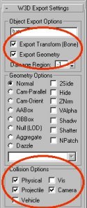
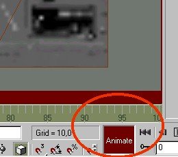


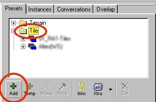
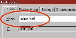
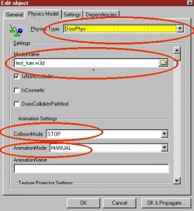
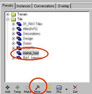
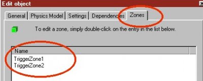
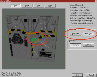
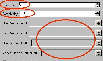
-
Author: danpaul88 Skill level: 3 Foreword Before I start, this is only the second tutorial I have ever written, so bear with me. I will try to cover all the possible pitfalls and things to watch out for, and explain each step in detail, if you think something needs clarifying or altering do let me know. Thanks. About this tutorial This tutorial will explain the use of WWSkin objects to animate meshes using their verticies, which can create effects that could never be achieved using standard animation techniques. This is how Tank Tracks are able to move up and down with their wheels, and can also be used on any other object. Before you start Some important notes about WWSkin that you should be aware of before you start trying to apply it; WWSkin animation ONLY works in RenX, as the 3DS Max version of the Renegade W3D tools does not support WWSkin. Therefore, if you model in 3DS Max you must export your model and import it into RenX to setup the WWSkin binding. UPDATE: Apparently it DOES work in 3DS Max, but it's harder to find. Once you have bound a mesh to a WWSkin you cannot change that mesh without removing the WWSkin first, otherwise RenX generally crashes. Therefore it is a good idea to save a copy before you start applying the WWSkin, so that you can go back to that if you realise you need to change something. The Tutorial I will use a simple tank tread as an example, taken a WIP version of the AR Chronominer. I have deleted all the other meshes in the scene to make it easier to see what's happening in screenshots. Before this I start explaining WWSkin you should know that the wheel bones are setup as normal, the wheels linked to the WheelC bones and those linked to the WheelP bones, which are at the same Z height as the bottom of the track mesh. These first two screenshot shows that the wheels moving up and down do not affect the position of the mesh, which would cause it to clip through the terrain. You should also note how the bottom of the Track mesh has been cut into slices as long as the gap between each wheel bone, we have to do this so we have vertices in the right place to link to the bones later on. Now that we have seen what happens without WWSkin binding applied to the treads, lets setup WWSkin binding and see what difference this makes. The first thing to do is create our WWSkin object, so go to the toolbar at the top and hit the button labelled 'Create a Renedage Skin' (yes, it really is spelt wrong in the W3D Tools). If your using 1024x768 like I am you will only about half of the icon, because it runs off the end of the toolbar, if you can't see it at all click on one of the || dividers on the toolbar and drag it to the left until it comes into view. For 3DS Max users If your using 3DS Max you can find the WWSkin object under the Spacewarps tab on the meshes section of the right hand side menu. Once you click the button you then have to click on your scene to create what looks like a set of crossed bones. Place this anywhere on your scene, it does not matter where, but if your using more than one on your scene it would be a good idea to place it somewhere near the mesh you are using it on. Select this new object and click the 'Add Bones' button on the right hand side. A window will pop up listing all the objects in your scene. You need to select all the bones that you will use to animate this mesh, and then click OK. In this example we are rigging a tank tread, so we need to choose all the WheelP bones for this tread. Once you have clicked OK they should appear in the list of bones for the WWSkin on the right. Ok, now that we have selected the bones that will be used in this WWSkin we have to link it to a mesh. You can only link one mesh to each WWSkin object, so if you need to animate multiple meshes you must create additional WWSkin objects. Bones can be used by more than one WWSkin object, so if a bone needs to move two or more meshes it can be linked to the WWSkin objects for all of those meshes. Select the 'Bind to Spacewarp' button on the toolbar (again, if like me your using 1024x768 this will appear off the end of the screen, click one of the | dividers on the toolbar and drag it to the left until you can see the button shown in the screnshot). Now click on your mesh, hold the mouse button, drag the icon to the WWSkin object and release, the same way you would to link objects to bones. The mesh should now have a 'WWSkin Binding' modifier on the right, and it's verticies will be highlighted. For 3DS Max users If your using 3DS Max the 'Bind to Spacewarp' button looks the same as it does in RenX, but is positioned on the far left of the toolbar, next to the buttons for linking and unlinking meshes. Handy Tip If your mesh changes position or size or does other wierd things when you bind it to the WWSkin hit undo the remove the WWSkin binding, and reset the meshes Xform by going to the Utilities tab (Hammer Icon) and choosing 'Reset Xform', and then click 'Reset Selected' with the mesh selected. This may turn your mesh inside out, if so go back to the Modify tab, select Polygon editing mode from the Editable Mesh dropdown, select all the polygons on your mesh and hit 'Flip Normal' to turn it the right way out again. You can then link to the WWSkin as normal Ok, now your mesh is linked to the WWSkin, the final step is to link the mesh vertices to their bones. Select the vertices that need to move with a particular bone, and then click 'Link to Bone by Name' on the right. Then simply select the bone to link them to from the list, and click OK. Select the next group of vertices to move with the next bone and do the same to link them to that bone, and repeat until all the vertices that need to move with a bone are linked to that bone. Each vertex can only be linked to a single bone. Note, you can also use 'Link to Bone' instead of 'Link to Bone by Name', which allows you to click a bone on the scene to link to, but I find it easier to use the object listing to do it. This is down to personal preference though. Once you are done linking vertices click the + icon next to the 'WWSkin Binding' and click the vertices text that comes up below this to allow you to deselect the mesh. You can only link vertices to bones that you previously added to the WWSkin object, if you need to add more bones select the WWSkin object and add them the same way we did earlier. The final result Ok, so what did we achieve by doing that? If you scroll up you will see the first image showed that moving the wheel bones up and down caused the wheel bones to clip through the mesh, so lets see what happens now that we have used WWSkin binding on the tread mesh to link it to the wheel bones. Create a 1 frame animation and move some of the WheelP bones up or down while in animation mode. The mesh will move with the bones, creating a much more realistic appearance. In our tread example, the treads will now fluctuate up and down with the terrain, instead of just being flat all the time. Exactly what we wanted to achieve. You can download my example file here to look at how it is setup, this is the completed gmax file I created while doing this tutorial. I trust that whoever created this simply tread for the Chronominer does not mind me using it for this tutorial example. WWSkin_Binding_Example.zip Footnote If you have any further questions, or suggestions to improve this tutorial, please do post them. I have tried to be thorough and cover the entire process from start to finish, but it is easy to forget to mention a step that seems obvious to you because you do it all the time, so if I missed something out please do mention it and I will update the tutorial. Good luck, and happy modding!
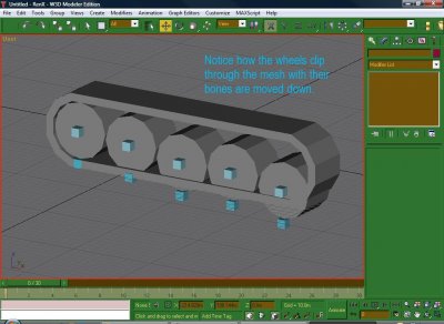
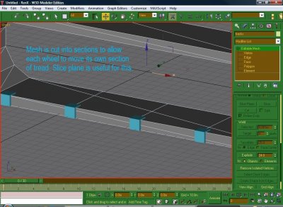

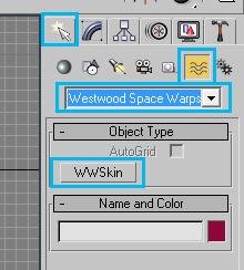
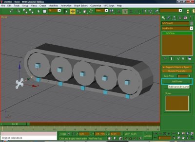
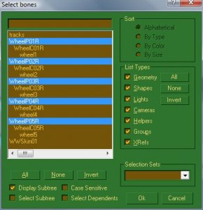
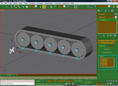
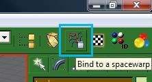
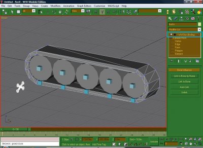
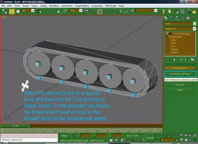
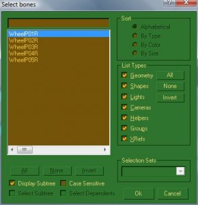

-
Author: Westwood Studios Skill level: 3 Here is a list of presets that are useful in text cinematic scripting. The presets can be found in LevelEdit if you need to see what the actual object is. CnC_GDI_MiniGunner_3Boss_ALT2 CnC_GDI_MiniGunner_3Boss_ALT3 CnC_GDI_MiniGunner_3Boss_ALT4 CnC_Ignatio_Mobius_ALT2 Mobius in Prototype Assault Suit CnC_Sydney_PowerSuit_ALT2 Ion Cannon Sydney in regular clothing CnC_Nod_FlameThrower_3Boss_ALT2 Mendoza in flamethrower clothing CnC_Nod_MiniGunner_3Boss_ALT2 CnC_Nod_RocketSoldier_3Boss_ALT2 Raveshaw mutant skin CnC_GDI_Grenadier_0_Secret Nurse with Grenade Launcher CnC_Visceroid Visceroid CnC_Nod_Flamethrower_0_Secret Cook with a flamethrower CnC_Nod_RocketSoldier_3Boss_Secret Kane CnC_Nod_RocketSoldier_3Boss_Secret2 Ghost of Raveshaw? CnC_POW_MineTimed_Player_01 CnC_Nod_RocketSoldier_0_Secret CnC_GDI_RocketSoldier_2SF_Secret CnC_Chicken --causes game to crash CnC_GDI_MiniGunner_2SF_Logan Logan CnC_Sydney_PowerSuit_Petrova CnC_Nod_FlameThrower_3Boss_Petrova CnC_GDI_Engineer_0 CnC_POW_MineRemote_02 CnC_POW_MineTimed_Player_01 CnC_GDI_Engineer_2SF CnC_MineProximity_05 CnC_POW_MineTimed_Player_02 CnC_GDI_Grenadier_0 GDI Grenadier (from single player?) CnC_Sydney Sydney from Single Player?? CnC_Ignatio_Mobius Mobius from Single Player CnC_GDI_MiniGunner_0 GDI Basic Infantry CnC_GDI_MiniGunner_1Off CnC_GDI_MiniGunner_2SF GDI Deadeye CnC_GDI_MiniGunner_3Boss GDI Havoc CnC_GDI_RocketSoldier_0 GDI Grenadier CnC_GDI_RocketSoldier_1Off GDI Rocket Soldier? CnC_GDI_RocketSoldier_2SF GDI Gunner CnC_Sydney_PowerSuit Personal Ion Cannon Sydney (in Prototype Assault Suit) CnC_GDI_Mutant_0_Mutant CnC_Nod_Mutant_0_Mutant CnC_GDI_Mutant_1Off_Acolyte CnC_Nod_Mutant_1Off_Acolyte CnC_GDI_Mutant_2SF_Templar CnC_Nod_Mutant_2SF_Templar CnC_Nod_Minigunner_0 Nod Basic Infantry CnC_Nod_Minigunner_1Off CnC_Nod_Minigunner_2SF Nod Black Hand Sniper CnC_Nod_Minigunner_3Boss Sakura CnC_Nod_RocketSoldier_0 CnC_Nod_RocketSoldier_1 Nod Rocket Soldier CnC_Nod_RocketSoldier_2SF Black Hand Rocket Infantry CnC_Nod_RocketSoldier_3Boss Raveshaw CnC_Nod_FlameThrower_0 Nod Flamethrower CnC_Nod_FlameThrower_1Off CnC_Nod_FlameThrower_2SF Nod Chem Warrior CnC_Nod_FlameThrower_3Boss Nod Mobius CnC_Nod_Engineer_0 Nod Engineer CnC_Nod_Technician_0 Nod Technician CnC_MineProximity_05 CnC_GDI_Grenadier_2SF CnC_Ignatio_Mobius_Skirmish GDI Mobius from Multiplayer Practice CnC_Sydney_Skirmish Tiberium AutoRifle Sydney from Multiplayer Practice CnC_GDI_RocketSoldier_2SF_Skirmish Gunner from Multiplayer Practice CnC_GDI_MiniGunner_3Boss_Skirmish Havoc from Multiplayer Practice CnC_GDI_MiniGunner_0_Skirmish GDI Basic Infantry from Mutiplayer Practice CnC_Nod_MiniGunner_3Boss_Skirmish Sakura from Multiplayer Practice CnC_Nod_RocketSoldier_3Boss_Skirmish Raveshaw from Multiplayer Practice CnC_Nod_MiniGunner_0_Skirmish Nod Basic Infantry from Multiplayer Pracice CnC_Nod_MiniGunner_2SF_Skirmish Black Hand Sniper from Multiplayer Practice CnC_Death_Powerup Crate that kills you when you go over it?? CnC_Crate_Powerup CnC_POW_Ammo_Clip01 crate that refills your ammo CnC_POW_Ammo_Clip02 crate that refills your ammo CnC_POW_Ammo_Clip04 crate that refills your ammo CnC_Money_Crate crate that gives you 100 credits M00_CNC_Crate ????? CnC_POW_AutoRifle_Player_GDI GDI Autorifle Spawn CnC_POW_AutoRifle_Player_Nod Nod Autorifle Spawn CnC_POW_RocketLauncher_Player Rocket Launcher Spawn CnC_POW_VoltAutoRifle_Player_Nod Mendozas Volt Auto Rifle Spawn CnC_POW_MineRemote_01 CnC_POW_MineRemote_02 CnC_POW_MineTimed_Player_01 CnC_POW_MineTimed_Player_02 CnC_POW_RepairGun_Player Spawn Repair gun CnC_MineProximity_05 CnC_POW_Ammo_ClipMax Pickup that maxes out your clips?? CnC_POW_Armor_Max CnC_POW_Health_Max CnC_POW_IonCannonBeacon_Player CnC_POW_Nuclear_Missle_Beacon CnC_Ammo_Crate CnC_Nod_Cargo_Drop CnC_Nod_Truck_Player_Secret CnC_GDI_Orca GDIs VTOL Orca CnC_Nod_Apache Nods Apache CnC_Civilian_Pickup01_Secret GDIs pickup truck (Extra)?? CnC_Civilian_Sedan01_Secret GDIs sedan (Extra)?? gdi_hovercraft GDI Hovercraft from Singleplayer (cannot be piloted) CnC_Nod_Transport Nod Transport Chopper CnC_GDI_Transport GDI Transport Chopper CNC_GDI_Gun_Emplacement GDI Gun Emplacement CnC_GDI_Humm-vee GDI Hummer CnC_Nod_Buggy Nod Buggy CnC_Rocket_Emplacement Rocket Emplacement CnC_Cannon_Emplacement Cannon Emplacement CnC_NOD_Gun_Emplacement Nod Gun Emplacement CnC_Nod_Ceiling_Gun Nod Ceiling gun---------- CnC_GDI_Ceiling_Gun Ceiling Gun from AGT CnC_GDI_Harvester GDI Harvester (doesnt include scripting) CnC_Nod_Harvester Nod Harvester (doesnt include scripting) CnC_GDI_APC GDI APC CnC_GDI_Mammoth_Tank GDI Mammoth Tank CnC_GDI_Medium_Tank GDI Medium Tank CnC_GDI_MRLS GDI Mobile Rocket Launcher System CnC_Nod_APC Nod APC CnC_Nod_Flame_Tank Nod Flame Tank CnC_Nod_Light_Tank Nod Light Tank CnC_Nod_Mobile_Artillery Nod Mobile Artillery Unit CnC_Nod_Recon_Bike_Player Nod Recon Bike CnC_Nod_Stealth_Tank Nod Stealth Tank CnC_Beacon_IonCannon Ion Cannon Beacon CnC_Beacon_NukeStrike Nuclear Strike Beacon CNC_Weapon_Flamethrower_Player Flamethrower Weapon CNC_Weapon_ChemSprayer_Player Chemsprayer Weapon CNC_Weapon_Orca_Rocket CNC_Weapon_Apache_MachineGun CnC_Weapon_Orca_HeavyMachineGun CnC_Weapon_Apache_Rocket CnC_Weapon_APC_M60MG CnC_Weapon_APC_M60MG_RedTracer Weapon_CnC_Ceiling_Gun_GDI CnC_Weapon_MineTimed_Player CnC_Weapon_MineTimed_Player_2Max CnC_Weapon_MineRemote_Player CnC_Weapon_MineRemote_Player_2Max CnC_Weapon_AutoRifle_Player CnC_Weapon_AutoRifle_Player_Nod CnC_Weapon_RocketLauncher_Player CnC_Weapon_RepairGun_Player_Special Weapon_CnC_Ceiling_Gun_Nod CnC_Weapon_RamjetRifle_Player Ramjet Sniper Rifle Weapon CnC_Weapon_SniperRifle_Player Deadeye`s Snipe Rifle CnC_Weapon_SniperRifle_Player_Nod Black Hand Sniper Rifle CnC_Weapon_IonCannonBeacon_Player Ion Cannon Beacon CnC_Weapon_NukeBeacon_Player Nuclear Strike Beacon CNC_Ammo_Flamethrower_Player Flamethrower Ammo CNC_Ammo_ChemSprayer_Player Chemsprayer Ammo CnC_Ammo_Orca_Rocket CnC_Ammo_Apache_Rocket CnC_Ammo_Apache_HeavyMachineGun CnC_Ammo_APC_M60MG CnC_Ammo_APC_M60MG_RedTracer CnC_Ammo_Orca_HeavyMachineGun Ammo_CnC_Ceiling_Gun_GDI CnC_Ammo_RocketLauncher_Player CnC_Ammo_RepairGun_Player_Special Ammo_CnC_Ceiling_Gun_Nod CnC_Ammo_RamjetRifle_Player CnC_Ammo_SniperRifle_Player CnC_Ammo_SniperRifle_Player_Nod CnC_Ammo_IonCannonBeacon_Player CnC_Ammo_NukeBeacon_Player CnC_Explosion_Shell_Rocket M00_Nod_Obelisk_CNC Weapon_Shotgun_Player Weapon_SniperRifle_Player Weapon_RocketLauncher_Player Ammo_Shotgun_Player Ammo_SniperRifle_Player Ammo_Chaingun_Player Weapon_Flamethrower_Player Ammo_Flamethrower_Player Weapon_Pistol_Player Ammo_Pistol_Player Ammo_GrenadeLauncher_Player Weapon_Chaingun_Player Weapon_GrenadeLauncher_Player Ammo_MineTimed_Player Weapon_MineRemote_Player Weapon_MineTimed_Player Ammo_RocketLauncher_Player Ammo_MineRemote_Player Ammo_MineProximity_Player Weapon_MineProximity_Player Ammo_ChemSprayer_Player Ammo for Chemsprayer Weapon Weapon_ChemSprayer_Player Chemsprayer Weapon POW_Pistol_Player This is the pistol you always have. Semi-auto, 12 shot clip. POW_Shotgun_Player This is the shotgun carried by Shotgun Troopers POW_SniperRifle_Player This is the Sniper Rifle carried by Black Hand Snipers and Deadeye POW_RocketLauncher_Player This is the Rocket Launcher carried by Rocket infantry. POW_MineRemote_Player The basic remote C4. POW_GrenadeLauncher_Player The GDI Grenade Launcher POW_Chaingun_Player The Officer Chaingun POW_ChemSprayer_Player The Nod Chemsprayer weapon POW_Flamethrower_Player Flamethrower POW_RepairGun_Player Repairgun (regular engineers) POW_IonCannonBeacon_Player Ion Cannon Beacon POW_LaserChaingun_Player Laser Chaingun (Black hand) POW_VoltAutoRifle_Player Volt Auto (Mobiuss) POW_RamjetRifle_Player The Ramjet Sniper Rifle (Havoc + Sakura) POW_LaserRifle_Player Stealth Black Hand Laser rifle POW_MineTimed_Player Timed C4 POW_MineProximity_Player Proximity C4 POW_AutoRifle_Player Basic Infantry Auto Rifle POW_PersonalIonCannon_Player Sydneys Pesonal Ion Cannon POW_TiberiumAutoRifle_Player Sydneys Tiberium Auto Rifle POW_TiberiumFlechetteGun_Player Patchs Tiberium Flechette Gun POW_Railgun_Player Raveshaws Railgun POW_AutoRifle_Player_Nod Nod Autorifle (Mendozas) POW_Chaingun_Player_Nod Nod Officer Chaingun POW_SniperRifle_Player_Nod Nod Black Hand Sniper rifle GDI_APC_Player GDI APC GDI_Humm-vee_Player GDI Hummer GDI_Mammoth_Tank_Player GDI Mammoth Tank GDI_Medium_Tank_Player GDI Medium Tank GDI_MRLS_Player GDI Mobile Rocket Launcher System Nod_APC_Player Nod APC Nod_Buggy_Player Nod Buggy Nod_Flame_Tank_Player Nod Flame Tank Nod_Light_Tank_Player Nod Light Tank Nod_Mobile_Artillery_Player Nod Mobile Artillery Nod_Recon_Bike_Player Nod Recon Bike Nod_SSM_Launcher_Player Nod Surface to Surface Rocket Launcher (DO NOT FIRE!!) Nod_Stealth_Tank_Player Nod Stealth Tank Nod_Gun_Emplacement_Player Nod Gun Emplacement Nod_Turret_MP Nod Defensive Turret Nod_Cannon_Emplacement_Player Nod Cannon Emplacement Nod_Rocket_Emplacement_Player Nod Rocket Emplacement Weapon_IonCannonBeacon_Player Weapon_LaserRifle_Player Weapon_AutoRifle_Player Weapon_LaserChaingun_Player Weapon_PersonalIonCannon_Player Weapon_RamjetRifle_Player Weapon_TiberiumAutoRifle_Player Weapon_TiberiumFlechetteGun_Player Weapon_VoltAutoRifle_Player Weapon_RepairGun_Player Weapon_StealthTank_Player Weapon_ReconBike_Player Weapon_MediumTank_Cannon_Player Weapon_MammothTank_Rocket_Player Weapon_MammothTank_Cannon_Player Weapon_LightTank_Cannon_Player Weapon_Humm-Vee_M60MG_Player Weapon_FlameTank_Player Weapon_Emplacement_Rocket_Player Weapon_Emplacement_Gun_Player Weapon_Emplacement_Cannon_Player Weapon_Buggy_M60MG_Player Weapon_APC_M60MG_Player Weapon_Railgun_Player Weapon_NukeBeacon_Player Weapon_SSM_Player Weapon_MRLS_Player Weapon_MobileArtillery_Cannon_Player Weapon_Chaingun_Player_Nod Weapon_AutoRifle_Player_Nod Weapon_SniperRifle_Player_Nod Weapon_Nod_APC_Player Weapon_VoltAutoRifle_Player_Nod Ammo_IonCannonBeacon_Player Ammo for Ion Cannon Beacon Ammo_LaserRifle_Player Ammo for the Stealth Black Hand Laser Rifle Ammo_AutoRifle_Player Ammo for the GDI Autorfile (Mendozas) Ammo_LaserChaingun_Player Ammo for the Black Hand Laser Chaingun Ammo_PersonalIonCannon_Player Ammo for Sydneys Personal Ion Cannon Ammo_RamjetRifle_Player Ammo for Havoc or Sakuras Sniper Rifle Ammo_TiberiumAutoRifle_Player Ammo for Sydneys Tiberium Auto Rifle Ammo_TiberiumFlechetteGun_Player Ammo for Patchs Tiberium Flechette Gun Ammo_VoltAutoRifle_Player Ammo for Mobiuss Volt Auto Rifle Ammo_RepairGun_Player Ammo for the Engineers Repair gun Ammo_RepairGun_Player_Alternate Ammo for Technician/Hotwires repair gun Ammo_StealthTank_Player Ammo for the Stealth Tank Ammo_ReconBike_Rocket_Player Ammo for the Recon Bike Ammo_MediumTank_Cannon_Player Ammo for the Medium Tank Ammo_MammothTank_Rocket_Player Rocket ammo for the Mammoth Ammo_MammothTank_Cannon_Player Cannon Ammo for the Mammoth Ammo_LightTank_Cannon_Player Ammo for the Light Tank Ammo_Humm-Vee_M60MG_Player Ammo for the Hummers Machine gun Ammo_FlameTank_Player Ammo for the Flame tank Ammo_Emplacement_Rocket_Player Ammo for the Rocket Emplacement Ammo_Emplacement_Gun_Player Ammo for the Gun Emplacement Ammo_Emplacement_Cannon_Player Ammo for the Cannon Emplacement Ammo_Buggy_M6C Ammo for the Buggys machine gun Ammo_APC_M60MG_Player Ammo for the APCs machine gun Ammo_Railgun_Player Ammo for Raveshaws Railgun Ammo_MobileArtillery_Player Ammo for the Mobile Artillery Unit Ammo_NukeBeacon_Player Ammo for the Nuclear Strike Beacon Ammo_SSM_Player Ammo for the SSM (DO NOT FIRE!!) Ammo_MRLS_Player Ammo for the Mobile Rocket Launcher System Ammo_AutoRifle_Player_Nod Ammo for Mendozas Autorifle?? Ammo_SniperRifle_Player_Nod Ammo for Nods Black Hand Sniper Rifle Ammo_Chaingun_Player_Nod Ammo for the Nod Officers Chain gun Ammo_Nod_APC_Player Ammo for the Nod APC Ammo_VoltAutoRifle_Player_Nod Ammo for Mendozas Autorifle?? CnC_GDI_Grenadier_0_Secret GDI Nurse with Grenade Launcher (Extra) CnC_Nod_Flamethrower_0_Secret Nod Chef with flame thrower (extra) CnC_Nod_RocketSoldier_3Boss_Secret CnC_Nod_RocketSoldier_3Boss_Secret2 CnC_Nod_RocketSoldier_0_Secret CnC_GDI_RocketSoldier_2SF_Secret CnC_Nod_Truck_Player_Secret Nod Cargo Truck. Cool! CnC_Civilian_Pickup01_Secret GDI Pickup Truck (Extra) CnC_Civilian_Sedan01_Secret GDI Sedan (Extra) Mx0_Nod_Obelisk Nod Ceiling Gun, can fire Obelisk laser PCT_Zone_GDI GDI Purchase Terminal. Functional, but does not show screen. PCT_Zone_Nod Nod Purchase Terminal. Functional, but does not show screen. Big_Gun_Phat GDI Costal Gun, add M05_Nod_Gun_Emplacement to make it shoot. M01_GDI_Gunboat A GDI gunboat, will shoot if given AI. GDI_A10_Flyover The GDI A10, nonfunctional. Nod_Comanche Sakura`s Comanche SignalFlare_Gold_Phys3 A Yellow-smoke Flare Create_Object Items To create these items, use Create_Object V_Jet A Nod VIP jet, cannot be flown. Enc_gcon GDI Construction yard?? V_Submarine A non-functional submarine V_Nod_Cargop_s The Nod C130 Cargo Plane Structures: To create these non-functional structures, use Create_Object, not Create_Real_Object enc_gbar GDI Barracks. Non-functional. enc_gbar Nod Airstrip wep#shunt This is the door of the weapons factory.... enc_gwep Weapons Factory, non functional. enc_gref GDI Refinery, non functional. Parachute Stuff: See Example H_A_X5D_ParaT_1 Animation of Parachute Falling X5D_Box01 Box attached to parachute by default, placeholder for items/units dropped by parachute X5D_Box01.X5D_Box01 Animation of the box falling with the parachute X5D_Parachute Parachute call name Scripts: M01_Hunt_The_Player_JDG This is the AI for the bot to hunt players in a game. M00_No_Falling_Damage_DME When bots or vehicles fall, they are not damaged M06_Thunder_Unit Makes bots drop rocket launchers when they die M00_Disable_Physical_Collision_JDG Vehicles can pass through barriers. Common Application M00_Damage_Modifier_DME","0,1,1,0,0" Makes it so that units cannot lose health (invincibility) Mx0_Obelisk_Weapon_DLS Makes units invisible. Not Stealth, true Invisible GTH_Credit_Trickle Modify the number of credits recieved per second. - ,"10" = 10 credits/second M05_Nod_Gun_Emplacement AI for turrets, good for non-skirmish bots also M05_Park_Unit A secondary AI for bots? M02_PLAYER_VEHICLE 90 sec AI for vechs dropped by c130, autopilots them off of Airstrip. M00_Disable_Transtition When attached to a vehicle, no one can get in that vehicle. This list was provided by Westwood Studios & kawolsky
-
Author: Westwood Studios Skill level: 3 By Greg Hjelstrom Introduction Renegade uses a form of rigid body dynamics to simulate a wide variety of vehicles. All of the geometric characteristics of a vehicle are determined directly from a model which is exported from 3ds-max. For example, the number, placement, and behavior of any wheels in the vehicle is determined by the set of bones in the model. Many wheel configurations can be defined by the model: front-wheel drive, four-wheel steering, all-wheel drive, tank tracks, etc can all be set up. Parameters such as the mass, engine strength, and suspension stiffness are set in the Renegade level editor. Balance The first thing to do is to position your vehicle model such that its center of mass is at the origin in MAX. In the X-Y plane, the CM (center of mass) should usually be placed exactly at the centroid of all of the wheels in the vehicle. If the CM behind this point, the vehicle will lean backwards on its suspension, if it is in front of this point, it will lean forward, etc. In the Z axis, the CM should be placed some distance below the center of the object to help prevent tipping over when turning corners. Collision Detection (WorldBox) As is the case with all objects in Renegade, you can use separate meshes for projectile collision detection and physical collision detection. In the case of vehicles you have to use a single OBBox named "WorldBox" for physical collision detection. (Note: physical collision detection is used when the object is moving in the world, projectile collision detection is used when the code is determining whether bullets hit the vehicle). For projectile collision detection, just use some representative meshes from your model. The WorldBox OBBox must be linked to the origin of the vehicle, and be aligned with the world axes. It should also be as small as possible while still containing the wheels and bulk of the body of the vehicle. The physics code in renegade collides with objects in a buffer zone near the surface of the worldbox so it should not completely contain the model. Below is a screenshot of a WorldBox. Note how the WorldBox does not extend all the way to the front, top or back of the vehicle. WorldBox checklist It should be named exactly "WorldBox" (or "WorldBox.00" when part of an LOD model) It should only exist in the top LOD of your vehicle It should be set up to export as an OBBox It should be Hidden It should have its Physical and Camera collision settings enabled It should be the only object in the vehicle model with Physical and Camera collision enabled It should be as small as possible while still containing the wheel contact patches in their initial position (more on this later). Wheels Wheels are defined by adding bones with a particular naming convention into your model. All vehicles, including VTOL aircraft, have wheels. At the bare minimum, there must be two bones per wheel; one to define the contact point of the wheel and one to define the center of rotation of the wheel. The code will use the pivot points of the wheel bones to determine the following things: the initial position of the wheel, the radius of the wheel, the axis that the suspension travels along, and the axis that the wheel rotates about. The two basic bones needed by each wheel are the "WheelP" (wheel position) bone, and the "WheelC" (center) bone. Below is a view of a wheel from the Humm-Vee model (with the WheelP bone selected). Note that the z-axis points along the direction of travel of the suspension and the x-axis points forward. Also, the pivot point of the WheelP bone must be contained inside the world-box. The initial position of all wheels should be at their extreme topmost point; imagine that the vehicle has just fallen off a skyscraper and landed directly on its wheels. Attached to the wheel position bone, you need a bone which defines the center of rotation of the wheel; the WheelC bone. Below is a view of a wheel with both bones set up. Again, the important axis is the z-axis, it points along the axis of rotation of the wheel; in the "Top" viewport in Max, the z-axis should be pointing down your monitor (for all four wheels). The graphical representation of the wheel is then attached to the WheelC bone and will rotate and translate as the vehicle is simulated. The simulation pays no attention to the graphical representation of the wheel or even whether it exists or not. The hierarchical linkage for a simple wheel should look like the one below. Note that the WheelC bone is attached to the WheelP bone; not the other way around. The `E` at the end of each of the names above is a flag signifies that this particular wheel applies the engine force at its contact point. Through this naming convention you can create four-wheel drive, front-wheel drive, or rear-wheel drive wheels. Other flags that are available include: S - The wheel will turn when the vehicle changes its steering parameter. I - The wheel will turn in the opposite direction of the vehicle`s steering parameter (rear wheel steering). E - The wheel will exert the engine force at its contact point L - The wheel is part of the left track of a tracked vehicle R - The wheel is part of the right track of a tracked vehicle F - The wheel is "fake"; it will graphically move with the vehicle but no forces are computed. The complete naming convention for a wheel bone is below. The name always starts with the word `Wheel`, followed by a single character and a two digit number (e.g. WheelP00). Following the digits, any of the above flags can be added. Wheel {P,C,T,F} {00} [E] [L] [R] [F] Here are some examples of valid wheel bone names: WheelP00ES - The contact point of wheel 00 which has the engine force and steering applied to it WheelC05 - The rotation axis of wheel 05 which only exerts a suspension force and rolls with the vehicle Advanced Wheel Settings You may notice that there are two more types of wheel bones that have not been described yet. These bones can be used to create wheels whose suspension moves in a manner more complex than simply translating along the z-axis of the WheelP bone. First I`ll show an example of a translational constraint using a WheelT bone. This example is from the front wheel of the Nod Recon Bike: The presence of the WheelT bone in a wheel hierarchy causes the wheel to translate along the Z-axis of the WheelT bone rather than the contact point bone. This is used for the front tire of the Nod Recon Bike. The rear wheel of a Recon Bike rotates along an arm. This can be accomplished by using a WheelF bone. Below is a picture of that situation. The WheelF bone will be rotated about its Y-axis to maintain contact between the wheel and the ground (see the picture for how to set it up). This is probably the most complex type of wheel to create... Look at the Nod Recon Bike for reference. Wheel Checklist Each wheel should have a bone named WheelPxx and WheelCxx (where xx is a two digit number) All wheel bones should have all W3D options disabled except for Export Transform The wheels should be positioned at their extreme topmost position (smashed into the vehicle) and their contact points must be contained inside the world box of the vehicle. The hierarchy should look like this: Origin->WheelP->WheelC->Graphical Wheel The Z axis of all WheelP bones should point along the direction of travel of the suspension The X axis of all WheelP bones should point towards the front of the vehicle (direction of rolling) The Z axis of all WheelC bones should point along the axis of rotation of the wheel (typically down in the Top viewport) All wheel bones should have their flags set (append an `E` to the wheels that are attached to the engine, append an `S` to the wheels that steer, etc) Turrets Vehicles can have turrets which can fire weapons. The turret aiming motion is generated by the game code as long as certain bones are present in the model. There are three types of bones involved in controlling a turret. The `Turret` bone will be rotated to set the turret`s `heading`. The `Barrel` bone will be rotated to set the tilt of the weapon. And the `Muzzle` bone will be used as the location to create projectiles from. Below is a picture of a the turret from the GDI Mammoth Tank: In the above picture, you can see that there are several muzzle bones. There can be up to two MuzzleA bones and up to two MuzzleB bones. [Generalcamo Edit: Current 5.x scripts now allow for a potentially unlimited amount of MuzzleA and MuzzleB bones] The `A` bones are used for the primary weapon of the vehicle and the `B` bones are used for the secondary weapon of the vehicle. All of the bones follow the convention that their axes should be aligned with the world axes; Z is up, X points towards the front of the vehicle, Y points to the left of the vehicle. If you create your boxes in the `Top` viewport, they will be oriented in this fashion automatically. One improvement over the linkage shown above would be to attach the V_Barrels mesh as a child of their Muzzle bones because the game engine automatically applies a recoil to the muzzle bone (attaching them in that way would cause the meshes to recoil when the weapon is fired). Turret Checklist The model should contain a `Turret` bone, a `Barrel` bone, and one or more muzzle bones (up to two MuzzleA and two MuzzleB bones [Generalcamo Edit: No limit in newest 5.x scripts]) The bones should be connected in the hierarchy shown above. Visible meshes in the model should attach to the appropriate bones so that they move when the game logic controls the turret (i.e. the turret mesh should be attached to the turret bone so that it will rotate properly) All of the bones should have their pivot points aligned with the world axes. All bones should have Export Transform enabled and Export Geometry disabled. Engine Special Effects VTOL vehicles can control bones to display engine effects. Here are some examples of engine effects: The flame on the Orca engine lengthens when the vehicle accelerates or climbs (EngineFlame) The Orca engine rotates forward and back as the vehicle accelerates or decelerates (EngineAngle) The rotors on helecopters spin when they are in flight (Rotor) Any bone present in the model which starts with the name "EngineFlame" will translate along its Z-axis along with the vehicle`s acceleration. Any bone present which starts with the name "EngineAngle" will rotate about its Z-axis. In the screenshot below, the EngineAngle bone for one of the Orca engines is selected. Below it is the EngineFlame bone and not shown is a skin which has vertices attached to both bones and stretches as the EngineFlame translates. Helicopter vehicles can use the EngineAngle bone to tilt their rotors as they fly forwards and backwards. In addition, they can contain `Rotor` bones which will spin about their Z-axis when in flight. The parameters for how much these bones rotate and translate are all controlled through settings in the level editor. Engine Effects Checklist "EngineAngle" bones will rotate about their Z axis "EngineFlame" bones will translate along their Z axis "Rotor" bones will constantly spin about their Z axis while the object is in flight Vehicle Damage As a vehicle becomes damaged, the game code can un-hide particular bones in your model. This can be used to show damage by attaching emitters to those bones since emitters in the model will start emitting when the bone they are attached to becomes un-hidden. There is support for three stages of damage, activated when the model reaches 25%, 50%, and 75% damage. When the model loses 25% of its health, all bones whose names begin with DAMAGE25 will be un-hidden. Once the object has lost 50% of its health, all bones whose names begin with DAMAGE50 will also become un-hidden. And when it has lost 75%, the DAMAGE75 bones will un-hide. Physics Parameters All of the actual physics parameters are controlled through the level editor. When creating a vehicle, the first thing you have to do is choose the physics model that it will use. There are four main physics models for vehicles: WheeledVehicle, TrackedVehicle, Motorcycle, and VTOLVehicle. Parameters common to all vehicles Mass - the mass of the vehicle GravScale - a scale factor that is applied to the gravitational force on the vehicle, normally should be 1.0. Elasticity - not currently used. AerodynamicDragCoefficient - controls the amount of drag. Spring Constant - spring constant for the suspension (even VTOL vehicles have a suspension) Damping Constant - damping in the suspension springs Spring Length - suspension length, wheels start at their initial position and can translate down this far Traction Multiplier - scales the amount of traction available to the vehicle Lateral Moment Arm - length of the rotational moment arm for lateral forces at the tire contact patches. this lets us fake the lean of the vehicle when turning without having to adjust the W3D model. TractiveMoment Arm - length of the rotational moment arm for tractive forces at the tire contact patches. This lets us control how much the vehicle "dives" when it brakes and how much it leans back when accelerating. EngineFlameLength - if the vehicle has an "EngineFlame" bone, this controls how far that bone will translate. Since this parameter is available to all vehicles (not just the Orca), we could create things like Recon Bikes and cars that have a flame emitting out of their engine. Parameters specific to ground vehicles MaxEngineTorque - this is the torque that the engine can output. For tracked vehicles we don`t have a sophisticated engine simulation; this torque is simply divided between the wheels and applied (also scaled by user input) EngineTorqueCurveFilename - this is the engine torque curve (relates torque to engine RPM). These curves are created with the "SimpleGraph" tool Gear Count - number of gears in the transimission GearRatio[0-6] - transmission gear ratios FinalDriveGearRaio - gear ratio in the differential DriveTrainInertia - inertia in the drive train components ShiftUpRpms - point at which the code shifts into a higher gear ShiftDownRpms - point at which the code shifts down to a lower gear MaxSteeringAngle - maximum angle of the steering tires LeanK0 - internal torsional spring constant for motorcycle "balancing" LeanK1 - internal torsional damping constant for motorcycle "balancing" Parameters specific to VTOL vehicles MaxHorizontalAcceleration - acceleration of the vehicle in the X-Y plane MaxVerticalAcceleration - acceleration of the vehicle along the Z axis MaxFuselagePitch - angle that the vehicle pitches when acclerating forward MaxFuselageRoll - angle that the vehicle rolls when strafing or turning PitchControllerGain - spring constant for the pitch controller PitchControllerDamping - damping constant for the pitch controller RollControllerGain - spring constant for the roll controller RollControllerDamping - damping constant for the roll controller MaxYawVelocity - how fast the vehicle can spin YawControllerGain - how fast the vehicle reaches its MaxYawVelocity RotorSpeed - how fast the `ROTOR` bones should spin RotorAcceleration - acceleration of the `ROTOR` bones RotorDeceleration - deceleration of the `ROTOR` bones

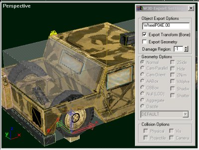
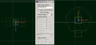
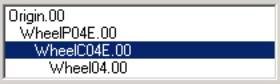

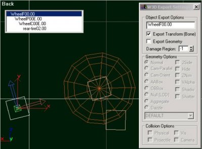

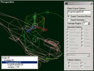
-
Author: Jonwil, moonsense715 Skill level: 3 Jonwil has just added a feature to scripts (4.2, 4.3 and 5.0) that lets you have a custom per-map loadscreen. Note: Players using versions without the feature will simply get the standard C&C mode loadscreen (so its safe to use even if you cant be sure all players will have 4.2). 1. Preparation Let's say you want a custom Loading Screen for a map named: TS_Paradise.mix. Get a scripts build that supports this feature from here. Copy its content to your game folder (not Data) and overwrite all. Create a file named TS_Paradise_map.ini. Inside this ini file put a [CustomBackdrop] section and underneath copy these values: ; This is a comment line ; TS_Paradise custom loading screen background image and texts [CustomBackdrop] 0=Model IF_LVL94LOAD 1=Color 100,255,100 2=Text2 50,17,IDS_LoadScreen_Item_00_Title ;Mission Title 3=Color 100,255,100 4=Text 60,40,IDS_LoadScreen_Item_00_Note ;Mission Overview 5=Wrap 350 6=Color 100,255,100 7=Text 60,60,IDS_LoadScreen_Item_00_Description ;Mission Summary 8=Color 100,255,100 9=Text 460,17,IDS_LoadScreen_Item_00_Text ;Mission Hint 11=Color 255,150,100 12=Text 106,155,IDS_LoadScreen_Item_01_Title ;1st Hint Title 13=Wrap 200 14=Color 255,150,100 15=Text 106,166,IDS_LoadScreen_Item_01_Text ;1st Hint Text 21=Color 255,150,100 22=Text 106,200,IDS_LoadScreen_Item_02_Title ;2nd Hint Title 23=Wrap 200 24=Color 255,150,100 25=Text 106,211,IDS_LoadScreen_Item_02_Text ;2nd Hint Text 31=Color 255,150,100 32=Text 106,245,IDS_LoadScreen_Item_05_Title ;3rd Hint Title 33=Wrap 200 34=Color 255,150,100 35=Text 106,256,IDS_LoadScreen_Item_05_Text ;3rd Hint Text 41=Color 255,150,100 42=Text 400,155,IDS_LoadScreen_Item_03_Title ;4th Hint Title 43=Wrap 200 44=Color 255,150,100 45=Text 400,166,IDS_LoadScreen_Item_03_Text ;4th Hint Text 51=Color 255,150,100 52=Text 400,200,IDS_LoadScreen_Item_04_Title ;5th Hint Title 53=Wrap 200 54=Color 255,150,100 55=Text 400,209,IDS_LoadScreen_Item_04_Text ;5th Hint Text 61=Color 255,150,100 62=Text 400,245,IDS_LoadScreen_Item_06_Title ;6th Hint Title 63=Wrap 200 64=Color 255,150,100 65=Text 400,256,IDS_LoadScreen_Item_06_Text ;6th Hint Text This is exact same stuff you would put in a loadscreen/backdrop entry in campaign.ini. 2. The background image Now look at the code again. 0=Model IF_LVL94LOAD This is the name of the model that shows during the loadscreen. Yes, W3D uses an animated model to show loadscreens and menu screens. (IF stands for InterFace)If you want a different picture as the background image, you will need a new W3D model that references the different "texture" on it. 3. Customize your background image You can download the source file of Reborn's loadscreen HERE. To alter the background image, you just need to change the texture that the material references. The same goes for the load bar texture. Export as hierarchical animated model with 60 frames. You can name it whatever you like but it should be unique and not match any other W3D file names. E.g. IF_LS_MYMAP.W3D should be free to use. Now if your model is named IF_LS_PARADISE.W3D, you put this to that first line in the load screen code: 0=Model IF_LS_PARADISE 4. The texts You can also replace the text to display custom strings, such as the title of the map, mission objectives and so on. Be careful though, the screen can load very fast for some users and they might not be able to read all the text you put there. For example, if you have a string: "IDS_LoadScreen_Paradise_Title" and it translates to "Welcome to Paradise!", then you simply put this: 1=Color 100,255,100 2=Text2 50,17,IDS_LoadScreen_Paradise_Title Now your new custom title will display, but of course only if that string exists in your custom strings.tdb. Example That's all. As a final example, here's what I created: My custom ini file: [CustomBackdrop] 0=Model IF_LS_PARADISE 1=Color 255,255,0 2=Text2 60,40,IDS_LoadScreen_Paradise_Title ;Mission Title Note that I changed the color and position of the text. Colors are RGB with values from 0 to 255, Text coordinates are offset from the top left corner of the screen. X. Bonus: Load screen for your game / mod Enjoy your new loadscreen!