

The AircraftPhys physics model is built on top of the VehiclePhys base model.
General Aircraft Physics
The translational physics of a CTOL (Conventional Take-Off and Landing) aircraft are based on four primary forces affecting the vehicle:
- Thrust
- Lift
- Weight
- Drag
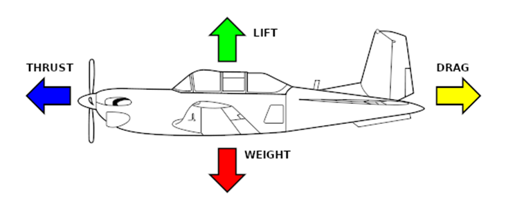
Thrust is the force provided by the engine of the aircraft, moving the plane forward. Lift is created by airflow meeting the wings, causing them to generate a force orthogonal to the wings (i.e in the direction that is "up" w.r.t the aircraft).
Drag is the airflow slowing down the aircraft while it is moving.
Weight is gravity pulling the aircraft toward the center of the Earth. When thrust is applied, the plane accelerates, creating airflow that can generate lift. Once the lift is strong enough, it becomes greater than weight, and the plane rises off the ground.
Drag increases as the plane speeds up, until it becomes as strong as thrust, and the plane cannot accelerate any more. Ideally, lift should be as strong as weight to allow the aircraft to maintain a stable altitude. Otherwise, the plane can reduce its speed in order to reduce lift, and thus achieve the same effect.
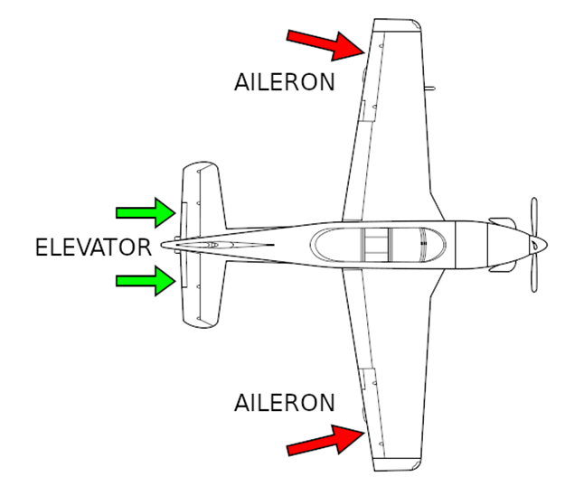
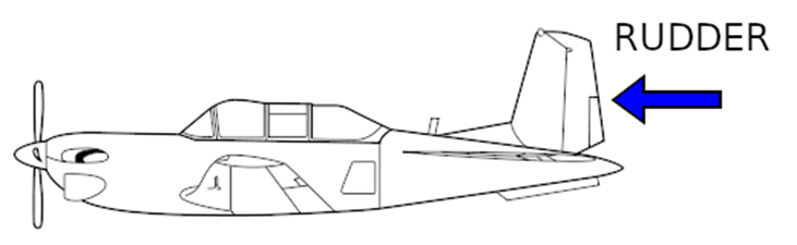
The rotational physics are affected by the aircraft's control surfaces (i.e "flaps"). These are:
- Ailerons
- Elevator*
- Rudder*
*Some planes may have two separate flaps performing this role together, but for our purposes, this is only a visual difference.
The behavior of the control surfaces is influenced by two factors: airspeed and the angle of attack (AOA), i.e the angle at which the airflow hits these surfaces. At a lower airspeed, there is less airflow hitting the surface, which means it exerts less rotational torque on the airplane.
If the airflow is parallel w.r.t the control surface, then there is negligible surface area for the airflow to exert force on, and thus no rotational torque is generated. This has two important consequences: firstly, our control surfaces inherently act as stabilizers, since whenever the airflow changes direction and is no longer parallel with these surfaces, a torque is generated that rotates the plane back into alignment with the airflow. This effect happens irrespective to control input, and is primarily created by the surfaces on the tail of the plane, similar to the fletchings on the back of an arrow (the wings may also generate a stabilizing torque, given a configuration that is covered below).
Secondly, by moving the control surfaces, we change the orientation at which they are parallel with the airflow, and can therefore generate torques to change the orientation of the plane. The key detail is that we are using an indirect effect: the plane does not generate the torque on itself, but instead makes use of the airflow, which leads to different behavior at different speeds.
The location and movement of the control surface determines the axis of rotation that they influence. The below image illustrates the axes of rotation and their respective names:

Ailerons are located on the wings, and thus influence rotation around the X axis, i.e roll. Elevator is located on the tail fins parallel with the ground, influencing rotation around the Y axis, i.e pitch. Rudder is located on the tail fin orthogonal to the ground, influencing rotation around the Z axis, i.e yaw. Each control surface also provides stabilization around the same axis. For example, if the plane is slightly tilted downward, but the airflow is coming parallel with the ground (due to the plane's momentum still carrying it in that direction), the elevator will try to tilt the plane back up, unless the pilot overrides the effect using the controls. In the case of roll, this only applies to certain aircraft: if the aircraft has dihedral wings (i.e they are angled in a "V" w.r.t the ground plane, an example would be the Yak in Red Alert), then the wings will attempt to roll the plane back into an orientation parallel with the ground, unless the pilot overrides the effect with the ailerons.
For our purposes, we do not use the full complexity of the aerodynamics of a real aircraft. For the flight surfaces, only three parameters are taken into consideration: angle, gain, and damping. The angle is set by the pilot as they use the controls, and as described above, the angle of the control surface w.r.t the airflow determines the rotational effects. "Gain" influences the strength of the reaction when a control surface is hit by airflow, so the higher the gain, the higher the turning rate around that particular axis of rotation.
To avoid making the plane uncontrollable, we also use "damping": once the plane's rotational velocity increases, the damping tries to oppose this and slow the rotation to a halt. The damping effect scales with the rotational velocity, so the faster we try to rotate the plane, the stronger this effect resists it, and thus sets an upper limit on rotational velocity. This is important because a plane could easily be made to turn faster than its momentum can change, causing the plane to "drift" in the air and potentially crash, or just be difficult to control in general.
Below is the list of parameters that can be tuned for all aircraft to change their flight characteristics:
|
Parameter |
Default |
Short Description |
|
|
0.0 |
Maximum thrust produced by the engine |
|
|
0.0 |
Maximum reverse thrust, used for reversing on the runway (not realistic, but necessary) |
|
|
0.0 |
Sets the throttle response speed, i.e how quickly we can throttle from 0 to 100% and back |
|
|
0.0 |
Sets an upper limit on the maximum speed of the aircraft |
|
|
0.0 |
Sets the rotation intensity for pitch |
|
|
0.0 |
Sets rotation damping for pitch, limits maximum pitching speed |
|
|
0.0 |
Sets the rotation intensity for roll |
|
|
0.0 |
Sets the rotation damping for roll, limits maximum rolling speed |
|
|
0.0 |
Sets the rotation intensity for yaw |
|
|
0.0 |
Sets the rotation damping for yaw, limits maximum yaw speed |
|
|
0.0 |
Lift coefficient, higher value means aircraft can achieve the same lift at a lower speed (i.e stay in the air while moving slower) |
|
|
0.0 |
Sets the strength of the brakes, helps stop faster on the runway |
|
|
0.0 |
Sets the maximum speed at which the aircraft can move when the landing gear is deployed |
|
|
false |
If set to "true", aircraft's wings are assumed to be dihedral, which means they automatically try to level out the plane if its wings are not parallel with the ground |
|
|
0.0 |
Sets the intensity of roll stabilization (see: DihedralWings) |
|
|
30.0 |
Sets the maximum angle that the aircraft's flaps can be rotated to (should be kept between 0 and 45 degrees) |
|
|
25.0 |
Sets maximum engine rotation (for visual effects only) |
|
|
360.0 |
Sets maximum rotor speed (for visual effects only) |
|
|
180.0 |
Sets rotor acceleration (for visual effects only) |
|
|
180.0 |
Sets rotor deceleration (for visual effects only) |
Mouse Steering
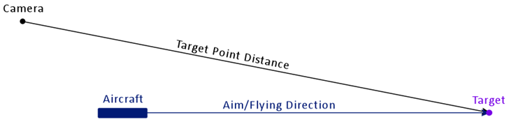
The mouse steering works by trying to steer the aircraft towards a point in space defined by where your camera is looking (see CTOL Aircraft#Target Point Distance below).
It is implemented using a CTOL Aircraft#PID Controller. The input to the steering system is the position of the target point
Note: All vector parameters are for Roll/Pitch/Yaw in that order.
|
Parameter |
Default |
Short Description |
|
|
|
Governs how much the plane directly responds to a discrepancy between the mouse steering target and the plane's orientation. |
|
|
|
|
|
|
|
|
|
|
|
|
|
|
|
|
|
|
|
Target Point Distance
The point in space your aircraft is steering towards is defined at a fixed distance in front of the camera (TargetPointDistance). This means that in order to fly straight ahead you need to point your camera slightly downwards (exaggerated here).
Care must be taken that the aircraft's weapon either has some turret tilt allowance or a tracking weapon. Otherwise, the discrepancy between the aircraft and camera positions and orientations can lead to the following issue:
Since the target point distance is fixed, the target may be behind or in front of what is currently visible in the center of the screen from the camera's viewpoint, for example a Tank you want to destroy, shown here in orange.
This means that the steering target from the aircraft's point of view does not cross through the Tank, which will cause a weapon with no turret tilt to misfire. The following images illustrate this in a slightly exaggerated manner.
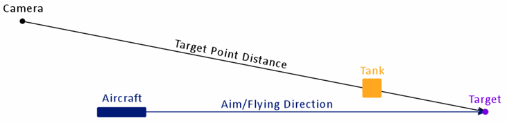

It is suggested to set TargetPointDistance to a rough estimate of the distance at which most aiming will take place, e.g. the weapon's range plus the camera distance.
This is much less of an issue for tracking weapons and the distance should not be set too short, otherwise the player will have to aim the camera further down to keep the plane flying straight ahead, which starts to feel weird at some point.
The camera profile should also not contain extreme values for camera height or distance in order to minimize the angle between the camera-to-target and aircraft-to-target vectors.
PID Controller
... describe what the properties of the 3 terms are and how to tune the parameters
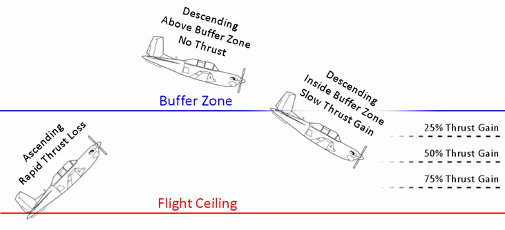
Flight Ceiling Behavior
The CTOL Flight Ceiling altitude is configured in the Level Settings. This part of the aircraft physics model can attach some additional behavior to each aircraft type while above the flight ceiling.
Normally, the aircraft loses all thrust when above the flight ceiling altitude, according to a rate defined by the parameter Thrust Loss. To mitigate the harshness of this ceiling, we can define a Buffer Zone above it.
The buffer zone allows the aircraft to slowly increase thrust again while descending, even though it is still above the ceiling. The thrust increase is applied automatically and is based on the ThrustGain of the aircraft.
|
Parameter |
Default |
Short Description |
|
|
|
Defines a buffer zone height above the CTOL Flight Ceiling (which is configured in the Level Settings). |
|
|
|
If an aircraft's Z velocity is lower than this threshold, it can activate the buffer zone's effects. Note that negative velocity means it is falling down, so negative thresholds make sense for this purpose. |
|
|
|
Thrust percent lost per second when above the flight ceiling and the buffer zone is not currently activated (i.e. Z velocity is above the threshold or altitude is above the flight ceiling + buffer zone). |


Recommended Comments
There are no comments to display.
Join the conversation
You can post now and register later. If you have an account, sign in now to post with your account.
Note: Your post will require moderator approval before it will be visible.