Search the Community
Showing results for tags '5 - Advanced'.
Found 13 results
-
5 - Advanced Overview: Full List of Human Animations in W3D
GeneralCamo posted a topic in Characters
Author: Jonwil Skill Level: 5 This is intended to be a guide to all the various human animations in W3D using the information we have collected in the process of figuring out the soldier logic. Animation styles Leg Styles: (the values are used as part of the animation name) LEG_STYLE_STAND A0 LEG_STYLE_RUN_FORWARD A1 LEG_STYLE_RUN_BACKWARD A2 LEG_STYLE_RUN_LEFT A3 LEG_STYLE_RUN_RIGHT A4 LEG_STYLE_TURN_LEFT A5 LEG_STYLE_TURN_RIGHT A6 LEG_STYLE_WALK_FORWARD B1 LEG_STYLE_WALK_BACKWARD B2 LEG_STYLE_WALK_LEFT B3 LEG_STYLE_WALK_RIGHT B4 LEG_STYLE_CROUCH C0 LEG_STYLE_CROUCH_MOVE_FORWARD C1 LEG_STYLE_CROUCH_MOVE_BACKWARD C2 LEG_STYLE_CROUCH_MOVE_LEFT C3 LEG_STYLE_CROUCH_MOVE_RIGHT C4 LEG_STYLE_CROUCH_TURN_LEFT C5 LEG_STYLE_CROUCH_TURN_RIGHT C6 LEG_STYLE_JUMP_UP J0 LEG_STYLE_JUMP_FORWARD J1 LEG_STYLE_JUMP_BACKWARD J2 LEG_STYLE_JUMP_LEFT J3 LEG_STYLE_JUMP_RIGHT J4 LEG_STYLE_FLY_STATIONARY Z0 LEG_STYLE_FLY_FORWARD Z1 LEG_STYLE_FLY_BACKWARD Z2 LEG_STYLE_FLY_LEFT Z3 LEG_STYLE_FLY_RIGHT Z4 LEG_STYLE_FLY_UP Z5 LEG_STYLE_FLY_DOWN Z6 Weapon Hold Styles: (again these are used as part of an animation name, yes these match the settings you set on the weapon in LE) WEAPON_HOLD_STYLE_C4 A0 A WEAPON_HOLD_STYLE_NOT_USED A0 B ; Actually used as the relaxed animation. ~~Jerad WEAPON_HOLD_STYLE_AT_SHOULDER C2 C ; Blended when an infantry moves aim up or down ~~Jerad WEAPON_HOLD_STYLE_AT_HIP D2 D ; Blended when an infantry moves aim up or down ~~Jerad WEAPON_HOLD_STYLE_LAUNCHER E2 E ; Blended when an infantry moves aim up or down ~~Jerad WEAPON_HOLD_STYLE_HANDGUN F2 F ; Blended when an infantry moves aim up or down ~~Jerad WEAPON_HOLD_STYLE_BEACON A0 G WEAPON_HOLD_STYLE_EMPTY_HANDS A0 H WEAPON_HOLD_STYLE_AT_CHEST B0 I WEAPON_HOLD_STYLE_HANDS_DOWN A0 J For weapon animations, the code can use this pattern H_A_?1$$/H_A_?2$$/H_A_?3$$ where ? is the second letter after the weapon hold style above and $$ is the value after the leg style. Or it can use the pattern H_A_??$$ where ?? is the first value after the weapon hold style and $$ is the value after the leg style. For landing animations (landing after falling/jumping) the pattern is H_A_A0L? where ? can be 0/1/2/3/4 depending on the direction. Actual animations Dive animations: (from a list in the code, dont know which one is which) H_A_SLD1_01 H_A_SLD1_02 H_A_SLD2_01 H_A_SLD2_02 H_A_SLD3_01 H_A_SLD3_02 H_A_SLD4_01 H_A_SLD4_02 Wound Animations: (from a list in the code, dont know which one is which) H_A_811A H_A_812A H_A_821A H_A_822A H_A_831A H_A_832A H_A_841A H_A_842A H_A_851A H_A_852A H_A_861A H_A_862A H_A_871A Death Animations: (from a list in the code, dont know which one is which) H_A_612A H_A_622A H_A_623A H_A_624A H_A_632A H_A_633A H_A_634A H_A_635A H_A_FLMB H_A_FLMB H_A_FLMB H_A_FLMB H_A_FLMB Ladders Ladders use H_A_412A, H_A_422A and H_A_432A Fire special damage uses H_A_FLMA Chem special damage uses h_a_6x01 Electric special damage uses h_a_6x05 Animation h_a_j12c is used when C4 is fired Other animations H_A_V20A is used as an animation when a soldier gets into a vehicle of type BIKE. H_A_V10A is used as an animation when a soldier gets into a vehicle that is not of type BIKE. The special Mendoza Boss object uses the animations H_A_FLMA, H_A_FLMB, H_A_H12C, H_A_A0A1, H_A_FLYKICK, H_A_CRESENTKICK, H_A_SIDEKICK, H_A_PunchCombo, H_A_690A, H_A_H11C, H_A_A0A0_L50 and H_A_635A. The special Raveshaw Boss object uses the animations H_A_BODYSLAM, H_A_FLY1, H_A_FLY2, H_A_FLY3, H_A_FLY4 and H_A_A0D0. The SSGM CTF plugin uses the animations H_A_SIDEKICK, H_A_PUNCHCOMBO, H_A_A0A0_L02, H_A_J22C, H_A_A0A0_L23, H_A_A0A0_L58, H_A_B0A0_L05, H_A_A0A0_L12, H_A_J14C, H_A_X33C, H_A_A0A0_L22 and H_A_A0A0_L24. The stock scripts.dll references the following animations: H_A_4243 H_A_442A H_A_601A H_A_611A H_A_613A H_A_622A H_A_632A H_A_6X01 H_A_6X05 H_A_7002 H_A_891A H_A_A0A0_L01 H_A_A0A0_L02 H_A_A0A0_L03 H_A_A0A0_L04 H_A_A0A0_L05 H_A_A0A0_L08 H_A_A0A0_L13 H_A_A0A0_L20 H_A_A0A0_L21 H_A_A0A0_L26DA H_A_A0A0_L26DB H_A_A0A0_L26DC H_A_A0A0_L28A H_A_A0A0_L28B H_A_A0A0_L28C H_A_A0A0_L32 H_A_A0A0_L34 H_A_A0A0_L36 H_A_A0A0_L51 H_A_A0A0_L52 H_A_A0A0_L53 H_A_A0A0_L56 H_A_A0C0 H_A_A0F0 H_A_A0L0_L51 H_A_B0C0 H_A_B22A H_A_B26A H_A_B91A H_A_B92A H_A_B93A H_A_Con2 H_A_FLMA H_A_H11C H_A_H13C H_A_HOST_L1A H_A_HOST_L1B H_A_HOST_L1C H_A_HOST_L2A H_A_Host_L2B H_A_HOST_L2C H_A_J01C H_A_J06C H_A_J11C H_A_J12C H_A_J13A - Start pushups H_A_J13B - Do pushups H_A_J13C - Finish pushups H_A_J14C H_A_J15C - Rotate neck/head around H_A_J18C H_A_J19A H_A_J19C H_A_J19S H_A_J21C H_A_J22C - Move/relax shoulders H_A_J23C H_A_J24C H_A_J26C H_A_J27C H_A_J33C H_A_TroopDrop H_A_V11A H_A_V42A H_A_X1E_Run H_A_X9C_SUIT H_A_X11D_Repel H_A_X33C H_A_X5D_ParaT_1 H_A_X5D_ParaT_2 H_A_X5D_ParaT_3 H_A_XG_NAPC_OUT Objects.ddb references animations in a few places (Human Loiter, Human Anim Override and some others) but I dont have the time to document all of them. In addition to this, the stock maps (Single Player specifically) may reference animations either through cinematics or through scripts attached to stuff but again I dont have time to document all of them. If anyone has any questions, wants more information or wants to know what the game does a specific animation (or what animation the game uses in a specific circumstance) please let me know and I will see what I can find out. Or if anyone has any info to add to this, feel free to add it here -
5 - Advanced Guide to new Lighting Features in scripts 4.x
GeneralCamo posted a topic in Miscellaneous
Author: Jonwil, Generalcamo Skill level: 5 Light solve improvements -Firstly, a bug has been identified in the vertex solve code related to meshes with bump mapping such as water. With the fixes provided by 4.0, you no longer need to hide water meshes before you run "compute vertex solve". -Secondly, another bug was identified whereby meshes that have no vertex colors and have an opacity of less than 1 set in their material settings would be treated as though the opacity was set to 1. This has been fixed The most well known example where the opacity bug can be seen is with the glass in the nod airstrip tower. With the new fixes, you will no longer need to hide any of the glass on the stock renegade buildings (including the air tower and the hand of nod) before you run "compute vertex solve". -Thirdly, 4.0 adds a new feature to the vertex solve code that lets you completely disable vertex solve on a particular mesh. This is intended for meshes where the vertex solve still screws up even with the above 2 features as well as for vertexes that contain pre-calculated lighting baked into the w3d file. (such as lightmap textures) To use it, you select the mesh in 3DS MAX and open the "Properties" dialog. Then you click on the "User Defined" tab. In that box you type "Prelit=true" (without the quotes). This will cause the vertex solve code to completly ignore this mesh (i.e. its essentially same as hiding the mesh before you vertex solve) The process is similar in Gmax/RenX. NOTE: If you are using the Prelit=true feature on a mesh that is part of anything other than terrain, ALL the meshes in that w3d file need to be Prelit=true otherwise it will screw up when you run the vertex solve. Buildings and lights Before we go into some of the deeper and more complicated stuff, here is some information about w3d you might need to know: Buildings have a prefix set in the building definition Meshes that contain the building prefix followed by the ^ character are exterior meshes for that building Meshes that contain the building preset followed by the # character are interior meshes for that building Buildings can also have lights associated with them. Lights will match the building if the name of the light (which is taken from the .wlt file, see below) matches with the mesh prefix of the building. Lights in Renegade can come from 2 places, they can be directly placed into leveledit or they can be placed via a .wlt file Every light in renegade has a "group ID" and a name. A .wlt file is a file that is associated with a terrain .w3d file and contains one or more groups of lights. When a .wlt file is loaded into leveledit, the lights are given names matching the .wlt filename. The first group of lights in the .wlt file are given a "group ID" of 0, the second group is given a "group ID" of 1 and so on. When a building is initialized, it creates 4 lists (actually 5 if you count the building aggregates but that doesn't matter for this discussion) and fills them with the appropriate data. The InteriorMeshes list contains all the interior meshes for the building. The ExteriorMeshes list contains all the exterior meshes for the building. The PowerOffLights list contains all the lights with a name that matches the building and a "Group ID" of 1. The PowerOnLights list contains all the lights with a name that matches the building and a "Group ID" of 0. Meshes can have "Alternate materials" associated with them. This is basically a second set of material data stored in the .w3d file. (this second set of data may contain textures, shader settings, material settings, texture coordinates etc) When a building is destroyed, the alternate materials on both the interior and exterior meshes are enabled. When a building goes low power, the alternate materials on the interior meshes are enabled. When a building is destroyed or goes low power, all the lights in the PowerOnLights list are disabled and all the lights in the PowerOffLights list are enabled. With these fixes, we have also identified how to make Alternate materials and alternate lighting work. The alternate material feature will only work properly on terrain and will only work on meshes that are prelit (i.e. those that have "Prelit=true" set) The alternate lighting feature will only work properly if the meshes being lit all have Prelit=true set. Meshes which do not have Prelit=true (and therefore get lighting from the vertex solve) will probably not look correct when the lights switch to the "power off/dead" set of lights. Using alternate lighting To use the alternate lighting feature you do the following: (there may be other ways to generate .wlt files, I am only describing the way I know to do it) Load leveledit and create a blank map Place the building interior terrain for the building you want to add lights to at 0,0,0 (i.e. so that 0,0,0 in the building terrain is at 0,0,0 in the level) Create any light presets you like and place them anywhere in the level (but presumably they will be inside the building). These will be the "normal" lights Choose Lighting-Export... from the menu. Save the lights as e.g. normal.wlt (the name doesn't matter, I am using normal.wlt for this example) You can (if you like) save this level with the placed lights in it for later further work if you like (you dont need to though) Delete all your "normal" lights Place your "dead" lights (which will also be used when there is low power) Choose Lighting-Export... from the menu. Save the lights as e.g. dead.wlt (the name doesn't matter, I am using dead.wlt for this example) You can (if you like) save this level with the placed lights in it for later further work if you like (you dont need to though) Put wltmake.exe, memorymanager.dll, normal.wlt and dead.wlt in a folder. Open a command prompt and go to this folder. Run wltmake out.wlt normal.wlt dead.wlt. Instead of out.wlt in that command, use the name of your building interior mesh but with a .wlt extension (so if the building is mabar_int.w3d, the wlt file would be mabar_int.wlt) Copy the new output wlt file into your always.dat file or whatever (somewhere LE and the game can find it) Edit the preset for your building interior terrain and set m_LightFilename to the name of your new .wlt file Repeat steps #1 to #13 for all the buildings that need special lights Once that is complete, open up each map that contains the newly-lit buildings. Delete any instances of the building interior meshes (or of any terrain that proxies them in) and re-insert them into the level so that the lights get pulled in. Save and re-export the map. Enjoy your new lighting (hopefully) Don't forget: you can always also use animated Tiles to hide/show different parts or versions of your buildings. Note: Lights will only be affected up to 50 meters from the building controller, so for large buildings try to center the building controller for best results. Using alternate materials To use the alternate materials feature you do the following: Take your mesh in max or gmax and apply the "normal/alive" materials (including any light maps you may have created) Export this to a w3d file (lets call it normal.w3d for this example) Edit the mesh and apply the "dead" materials (including any light maps you may have created) Export this to another w3d file (lets call it dead.w3d for this example) Put both w3d files, memorymanager.dll, altmat.exe and w3dlib.dll in a folder. Open a command prompt and go to this folder. Run altmat out.w3d normal.w3d dead.w3d replacing out.w3d with the name of the output mesh you want (i.e. the name that matches the building you are working with) Place the new w3d file in a place that leveledit and the game will find it. Export your maps as normal Load the game and enjoy your new materials The things you can change between normal and dead materials are: -Vertex colors -Texture coordinates -All the values on the Vertex Material tab -All the values on the Shader tab -All the values on the Texture tab EXCEPT for the "Stage 0 Texture" and "Stage 1 Texture" checkboxes Changing anything else (including geometry or pass counts) will not work and may lead to crashes (in altmat or in the game). Remember that you can't rename a w3d file so make sure you use the correct output filename. -
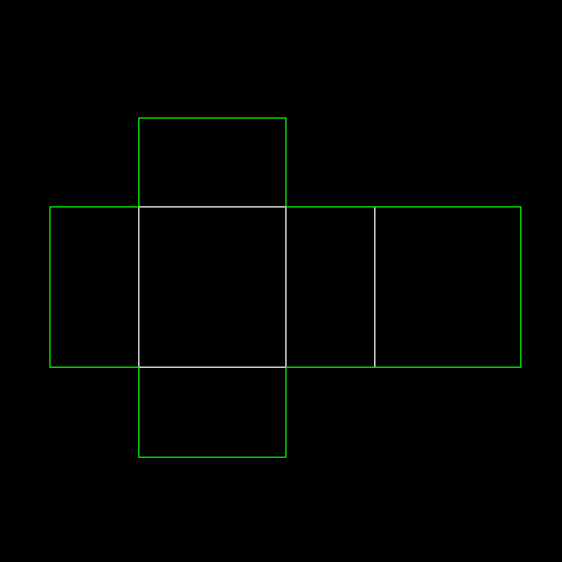
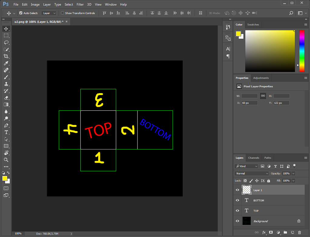
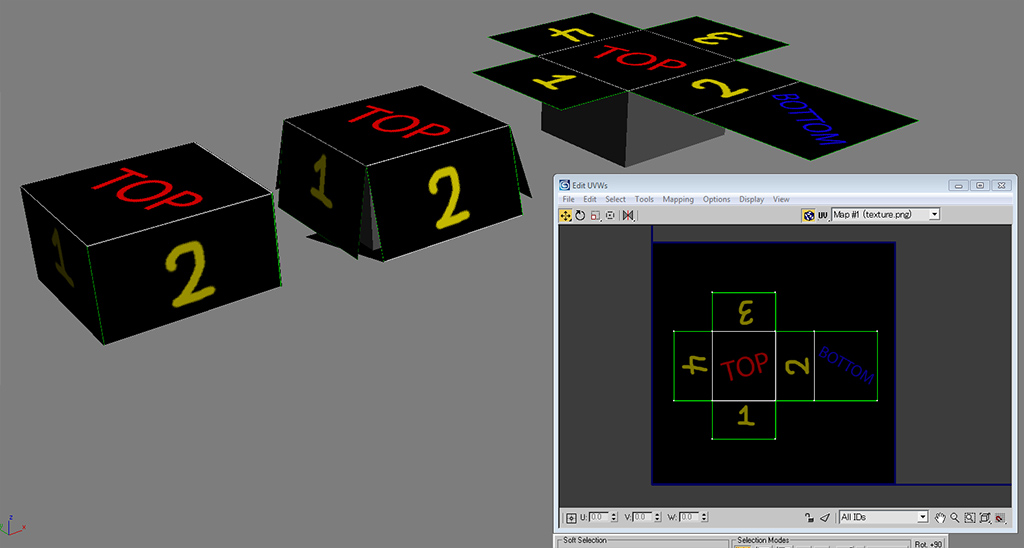
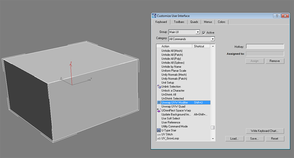
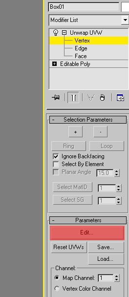
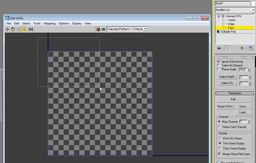
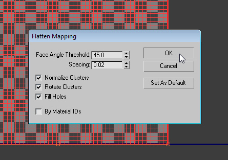
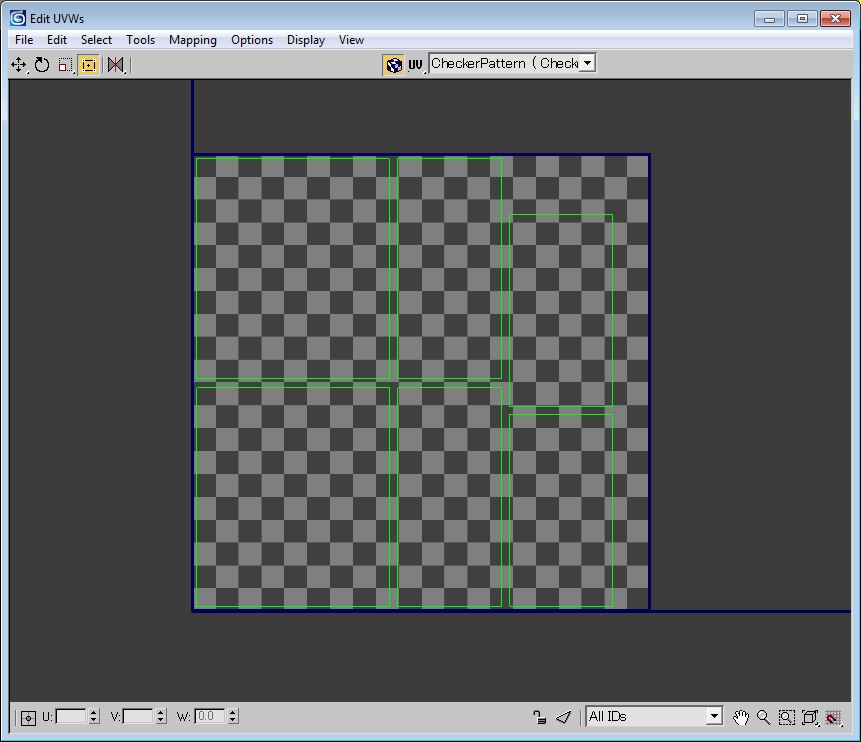
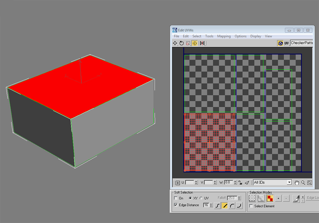
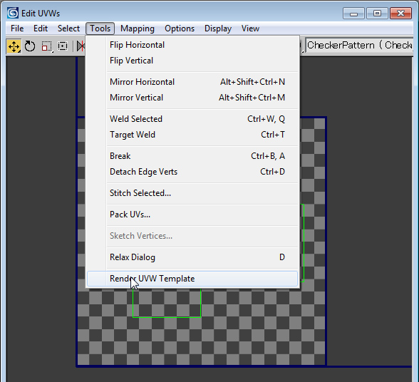
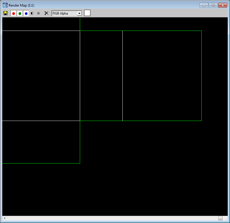
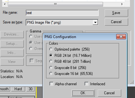
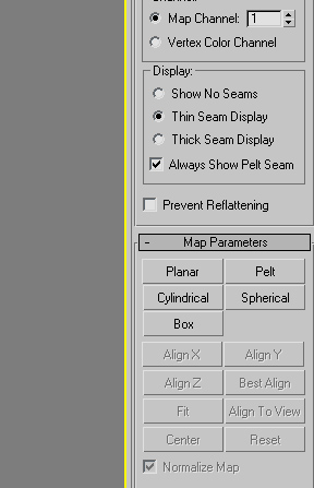
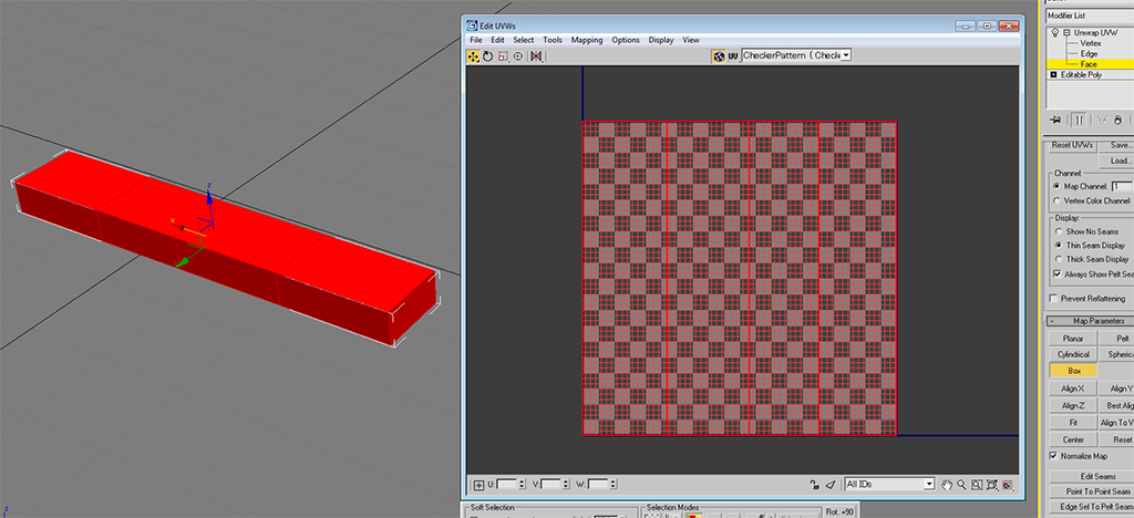
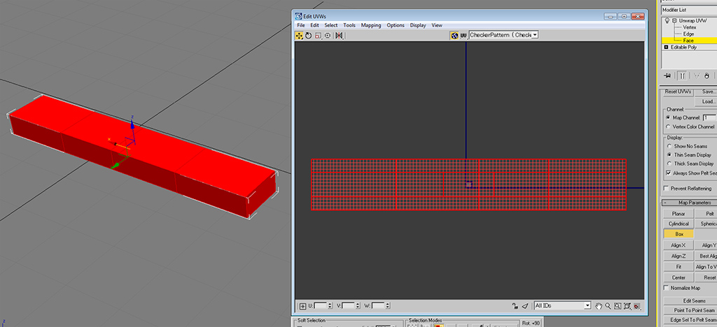
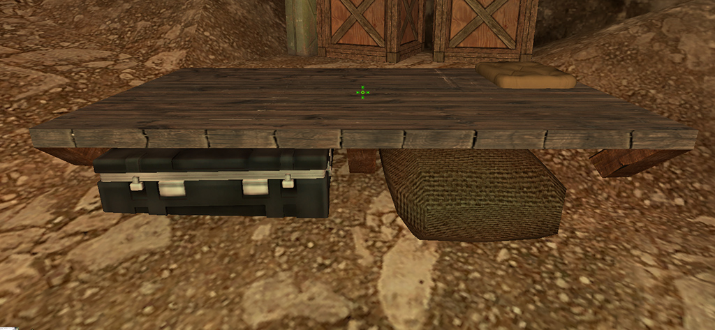
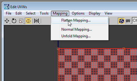
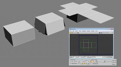
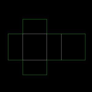
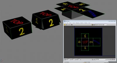
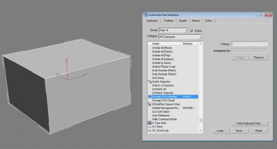
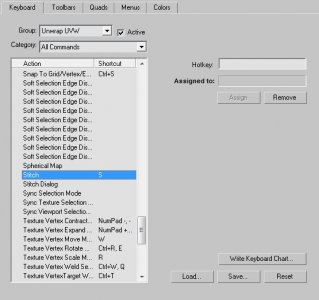
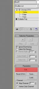
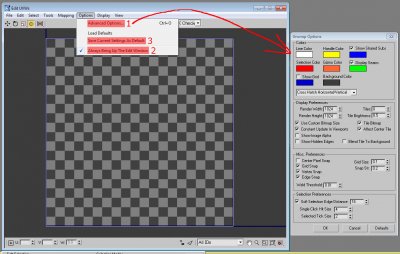
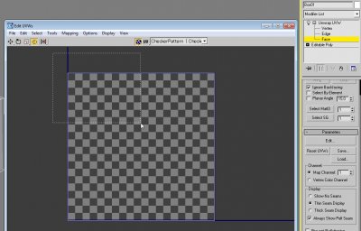
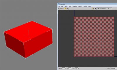
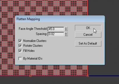
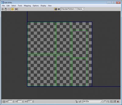
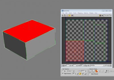
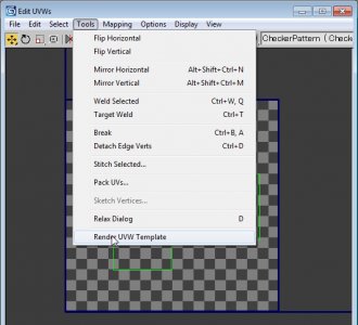
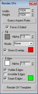
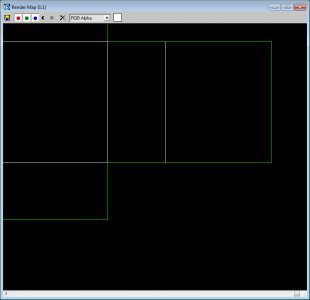
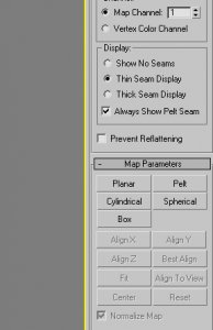
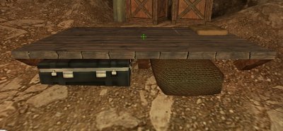
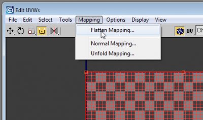
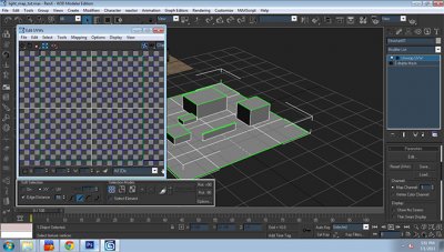
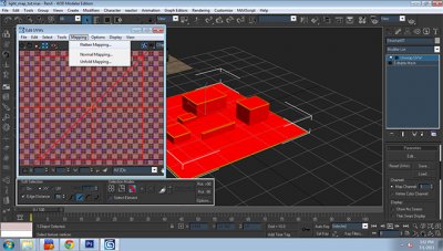
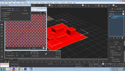
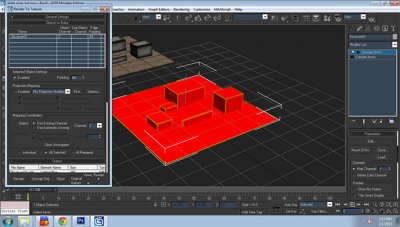
So you've modeled an object. It's probably gray or some assortment of solid colors, and if you're reading this, what you're likely wanting to do is apply stylized texturing to your object using Photoshop or some other 2D imaging program, and you either don't know how to do that yet or want to learn a few more tips to up your game. If you would rather watch a video tutorial, use this: https://w3dhub.com/forum/topic/414495-uvw-unwrapping-101-with-owa/ Otherwise, read on! This tutorial assumes a solid basic understanding of 3DS Max 8, and I will use "Photoshop" to mean whichever 2D imaging program is applicable in your case. Before we go through the tools and buttons, it would be good to provide a general outline of unwrapping and its process. I suppose the easiest way to explain it is to compare your object to a Christmas present. Imagine it is a box shape that already has wrapping on it. The wrapping is white paper and doesn't have any color on it, so you need to unwrap the present, put the wrapping on a flat table, color it, then wrap it back onto the present. The same principle applies no matter the complexity of the object. Every polygon needs to be able to be laid flat across the table. Sometimes this involves cutting parts up, which is where we get seams (useful on a lot of angular, manmade objects), and sometimes this involves slight texture stretching if seams are to be avoided (more organic or fluidly-shaped objects). The image above illustrates the principle of unwrapping a cuboid and what that unwrap would look like in the UVW edit window. The blue box in the UVW edit window indicates the boundaries of the square texture file that you will see in Photoshop. What is seen in this window can be rendered to a PNG file that will be loaded as a background layer in Photoshop, which can then be painted on. Here it is, with the texture brought back into 3DS Max. For W3D projects, the texture file would be saved as .dds and applied as a W3D material. Obviously, the UVW template background layer would also be hidden so as not to show the lines of edges and green seams in the final product. Now, HOW to do the unwrapping in 3DS Max? Glad you asked! Because of how often I do this, I set up a keyboard shortcut and I recommend you do the same (assuming you haven't imported chopbam.kbd previously, of course). Set Unwrap UVW Modifier to Shift U. Also set stitch to S. Now select your object and press Shift U. Being as familiar with 3DS Max as you undoubtedly are, you will notice that it created a modifier. Expanding this modifier you will see "Vertex," "Edge," and "Face": modes that are similar to the subobject modes in the Editable Poly mode. You can press 1, 2, and 3 to cycle through Vertex, Edge, and Face, and press the same button again to go out into the general Unwrap UVW modifier. Press "Edit..." to bring up the UVW edit window we saw above. You'll want to generally always have this window open while doing your unwrapping work. ***For future reference, the UVW unwrap you see in the window by default would be the result of any unwrap if you select all and hit "Planar" in the command panel. There is an invisible eye in the sky that looks straight down on your object on the Z axis and throws a normalized (stretched to fit the blue square) version into the UVW edit window. Unless you're unwrapping a flat plane, this is not the look you'll want in the end, but it's just the default view. These are the options I use. Sometimes things change based on the need. You'll definitely want the render width and height to match your planned texture resolution. I "Always Bring Up The Edit Window" because unwrapping is useless without it, and it saves me the step of clicking "Edit..." every time. "Save Current Settings As Default" saves me time later, since I like my preferences and don't want to have to set them every time I apply an Unwrap modifier, which is very often. Let's move forward into actually unwrapping. With face mode selected, you'll want to select all your faces. By default, all the polygons are normalized/stretched to fill the UVW square. Draw a box or Ctrl A to select all polygons. You can also select your polygons on the model itself, but keep in mind "Ignore Backfacing" is enabled by default, so unless you uncheck that box in the "Selection Parameters" rollout, that method will only select polygons facing you in the viewport. There are a bunch of ways to tell the program how exactly to cut up your 3D model's wrapping and flatten it onto the table, but the way I'll show you right now is to go to Mapping -> Flatten Mapping and hit OK. Here is the resulting unwrap for me. Find the top. In face mode select the top of your object so you know which poly that will be in the edit window. Now in edge mode, select the edges of the top and press "S" to automatically stitch the polygons on the corresponding sides. You'll see in the GIF below that I'm quickly switching between move and scale, and I'm doing that using the W and R keys. E is for rotate. I don't remember if these are set by default, so you may need to check your options. Note: If selecting individual subobjects isn't working right, and it's selecting the entire element, try unchecking "Select Element" on the panel docked below the edit window. Tip: Unfold mapping might do this automatically for you with a box, but I did flatten mapping to show the principle of stitching, which is a real time saver with more complicated objects. Now to render this out as a UVW template to get into Photoshop, go to Tools -> Render UVW Template. It will only render inside the blue square. The main thing is to make sure Width and Height match the exact texture resolution you want to use. For W3D projects, we use 512*512 for small objects, 1024*1024 for medium objects, and 2048*2048 for high resolution, newer objects like APB's redone vehicles. Keep in mind you can also use multiple textures for your object, so that'll require multiple UVW templates. Once you hit render, you'll see your render map. If it's a bit larger, it'll be scaled down by default but you can use your mouse wheel to zoom in and examine your beautiful UVW template. Save UVW template and I usually just save as a PNG. Alpha not really necessary since it's used as a background layer. Now you can work with the layer in Photoshop. Put other layers on top of it. If you set them to "Screen" or "Lighten," you'll always be able to see the UVW template through your drawn pixels and use them as a guide for where your poly edges are. For more complicated objects, flatten mapping might not always be the way to go. You'll see there are a number of map parameter options in the command panel. You can use them as alternate ways to project UVW coordinates (the term I use to denote the connection between the polygon itself and its 2D counterpart in the unwrap). These tools are for more manual work. Select the faces you want to set UVW coordinates for, and then go to work. Each tool is self explanatory. Planar acts as an eye that looks on the X, Y, or Z direction (depending on which button you press). Cylindrical works well for cylinders. Box does guesswork and lays a good groundwork for stitching, in my opinion. A few tips. 1) Always uncheck "Normalize Map." This will stretch and distort the texture to fit exactly into the square edges, and you don't want that. You want uniform scaling. Whenever I uncheck it, my polygons and elements in the edit window get really huge. Make sure to scale them down later. On this long plank, that will mean the difference between: and You will see that in the first image, the long plank is forced into a square, whereas the second image, the UVW polys are much more consistent with the shape of their object (and that the UVW elements are HUGE). I usually wait until everything's been mapped to scale down, so all my elements get scaled down uniformly. If I scale a pipe down, but not as much as the thing it's attached to, they will have different texel densities, or resolutions, and look inconsistent. 2) Maximize your UVW space. Try to eliminate as much negative space as possible by filling up the blue square with UVW elements. Otherwise you will end up with unnecessarily wasted texture space that goes into the game. 3) Provide sufficient texel density. Pretty much a no-brainer, but probably should be covered anyway. Make sure your texture has enough resolution to actually look good ingame. If elements are small, obviously they won't need as much texture detail. If elements will be large and close up ingame, you will want them to have more texture detail. 4) Use unwrapping to fix existing errors. If existing stretching needs fixing, or seams don't look quite right, or you want to rotate that wooden plank so it's going down the board (example below), you can use an unwrap modifier to fix it. Something like this would be fixable by opening the edit window, selecting that face, then using the rotate and move tools to put it into its proper place. Further tweaking can be done to the individual UVW vertices. 5) If you collapse your modifier stack, you can always get your unwrap data back later by applying another modifier with Shift U. It even saves multiple channels. If you applied a UVW map modifier to terrain but wish to fix just one spot, collapsing the stack and then applying a UVW Unwrap is for you. You can look in realtime as you adjust vertices in the Edit UVWs window and see how it's affecting the texture in the viewport. 6) If you're wanting to show your texture in the Edit UVWs window, click the CheckerPattern dropdown near the top and select your texture (assuming it's been applied through the material editor). You may need to Reset Texture List to get it to show. 7) Check out the Tools available. In the Tools dropdown, see what else you can do, from welding to mirroring to breaking vertices to relaxing, it's all there and extremely useful. Play around with it and see what you can do! You've probably also noticed the buttons for Saving and Loading UVWs, which do seem to work as expected. If you save UVWs out to a file, you can Load them into a different Map Channel. I hope this tutorial has been helpful! Write here if you have questions or comments or tutorial bug reports and I'll do my best to answer or amend any issues.


-
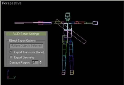
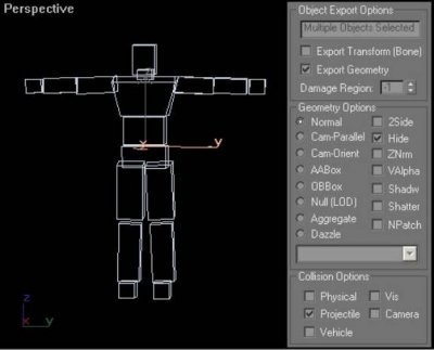
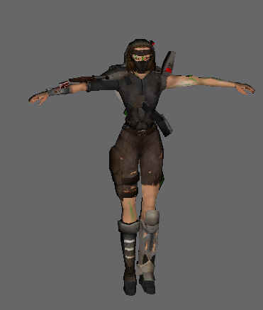
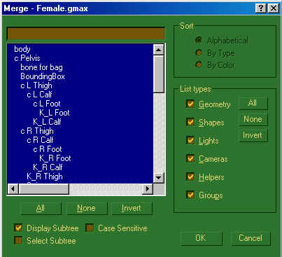
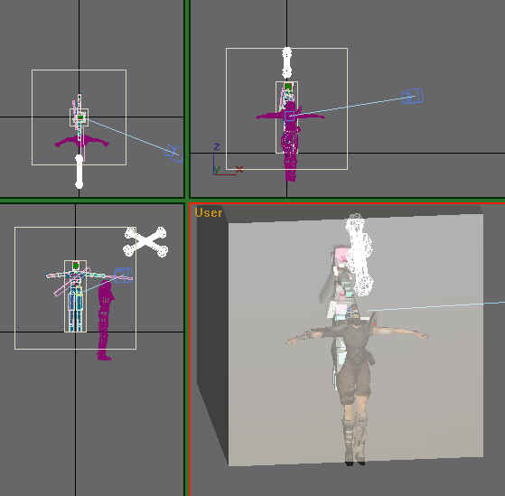
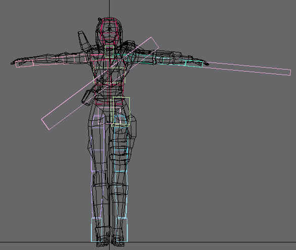
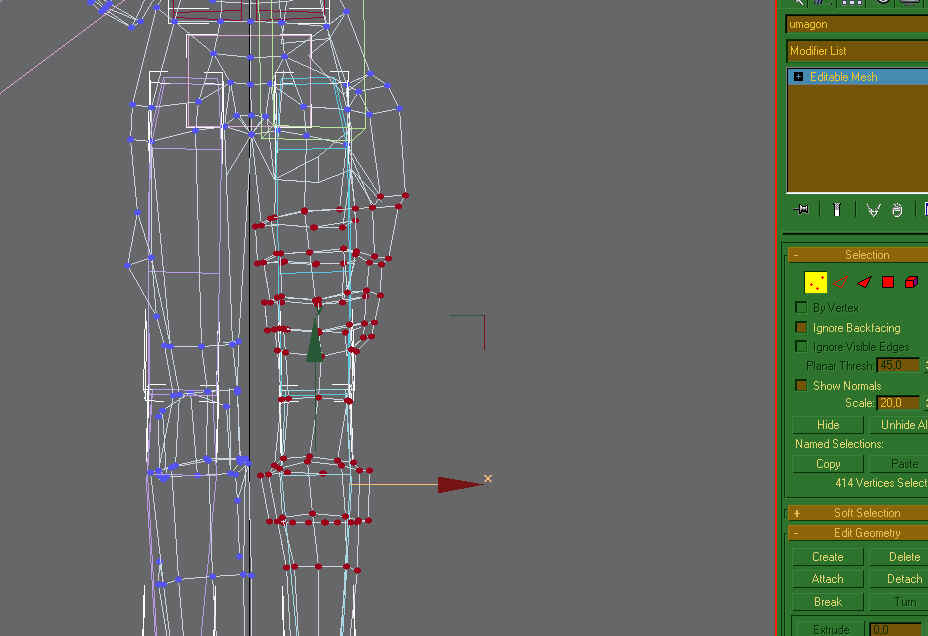
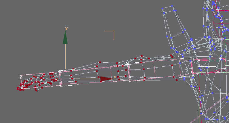
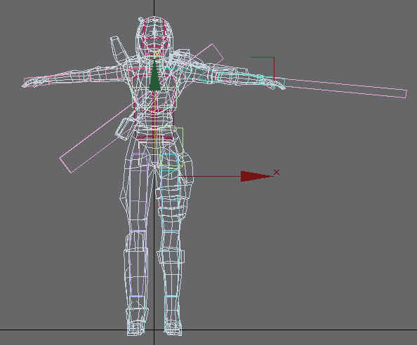
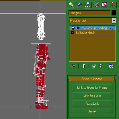
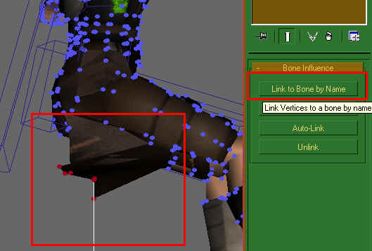
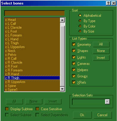
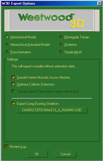
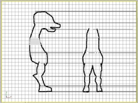
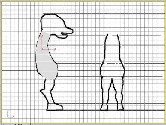
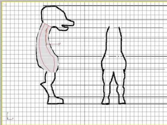
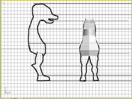
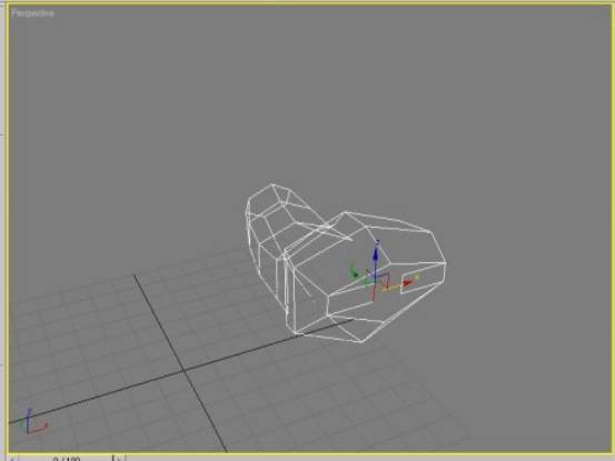
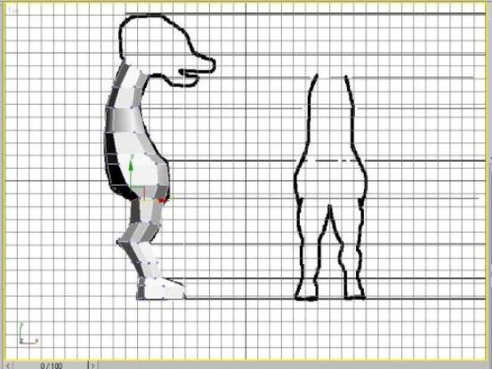
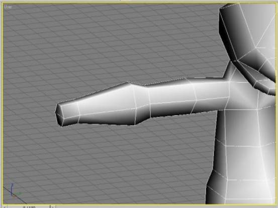
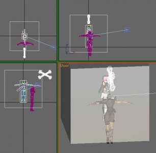
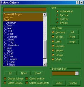
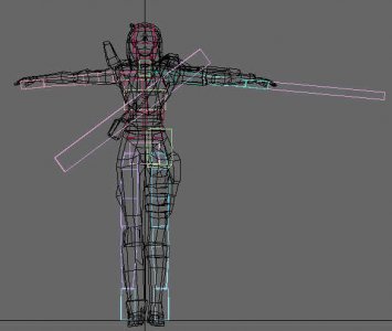
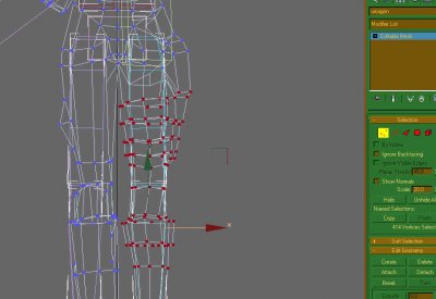
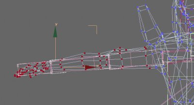
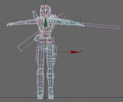
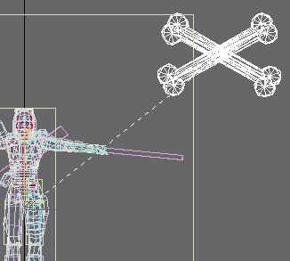
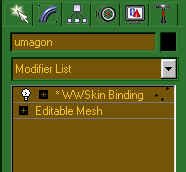
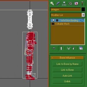
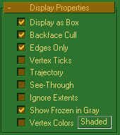
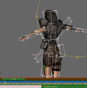
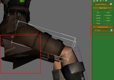
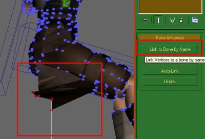
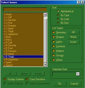
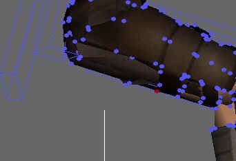
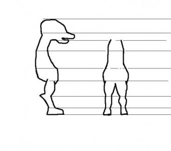
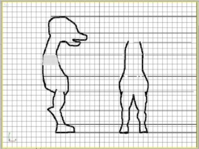
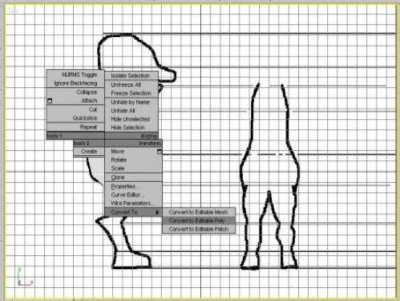
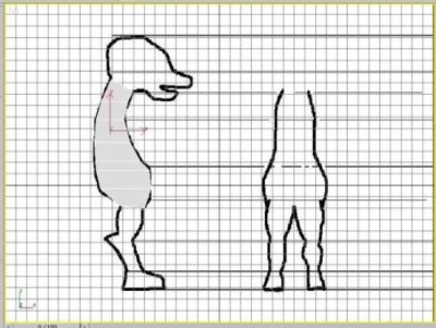
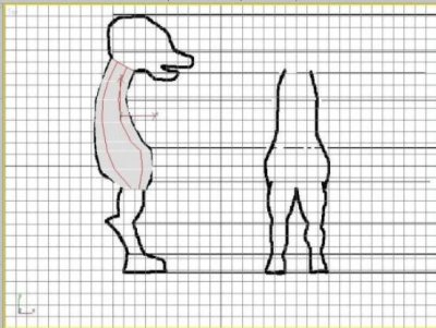
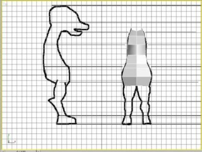
Author: Läubi Skill level: 5 This written tutorial will show you how to make your character model ready to be used in the W3D engine. Step 1 First we need our Character, here you can see the Umagon from Reborn Step 2 Then we need the Skeleton, depending on what Character-type we have, import either the Male or the Female character (Here you can download: Female skeleton, Male skeleton) Select All and press Ok. Step 3 Now we need to align and resize the character, because in most cases it will look like this: To make your life easier, you should hide all K_ bones and the old mesh, as well as the Worldboxes Try to align the character as closely as possible to fit the bones!! Step 4 Tweak up the base position, so the character fits the bones. As you saw on the previous screenshot the arms and the feet/legs don`t fit that good, so we need to align them, so hope that the creator of the model has already designed the model to fit, otherwise you'll have a lot of fun trying to align it properly It is very important that you align it as close as possible, as that will make your life a lot easier later and will reduce the amount of animation errors you later might get! Now it fits the bones a lot better: Step 5 Unhide all parts, delete the merged Head and body mesh. The female file also contains a camera object that you can delete as it's not needed. If you have not done it yet, save your work into a new file Step 6 Now we will Link the Mesh to the WWSkin (that's the small CrossBone) by selecting: and the click on the mesh and drag to the WWSkin: Now the model has the WWSkin Binding Modifier applied, we will now use this to bind the vertices to the bones: Select all vertices and press on the Auto-Link Button Congratulations, the smart part is done now Step 7 Time for fixing errors, or did you think it is THAT easy??? For better working on the next steps you can again hide all the K_ Bones the Worldbox, the select all the c_ bones and activate the Display as Box option: Now move the animation slider to Frame 1. You will notice that your Character moves. Move through the different frames and watch out for any misaligned faces. Select the Bone the faces "should" be aligned to. Here it is the correct bone, write it down, or remember it, and select the misaligned faces, and click on Link to Bone by Name: Find and select the bone the faces belong to: Press Ok and if your faces are aligned right, well done. Repeat these steps until all faces are aligned correctly. Step 8 - Export your final result Export it with following Settings: Female Characters use S_B_Human as existing skeleton: Male Characters use S_A_Human: You find the needed Skeleton Files in the corresponding folder from where you have merged the skeleton file. Now you can test the Character In-Game and see if there are any other problems you might need to fix. Have fun on your hard way!


-
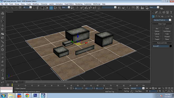
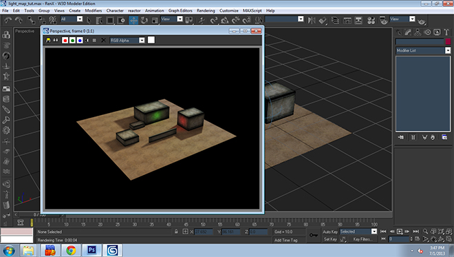
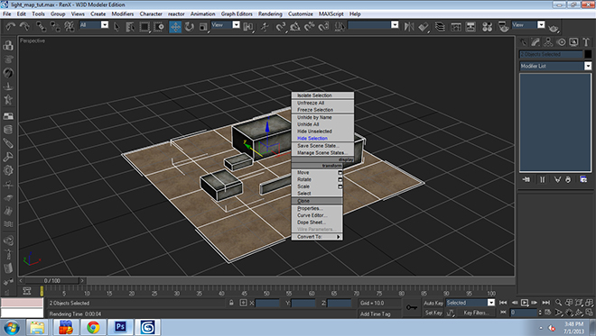
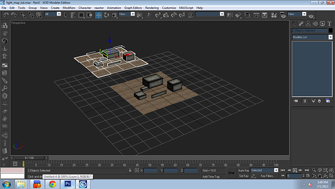
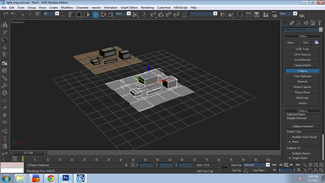
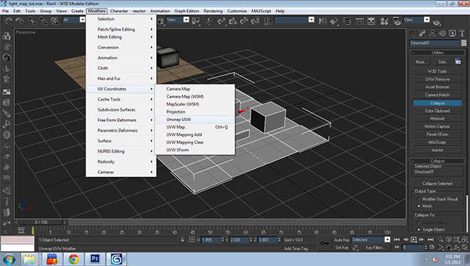
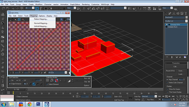
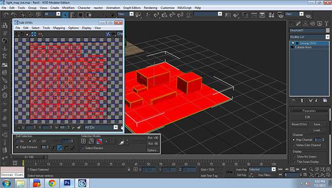
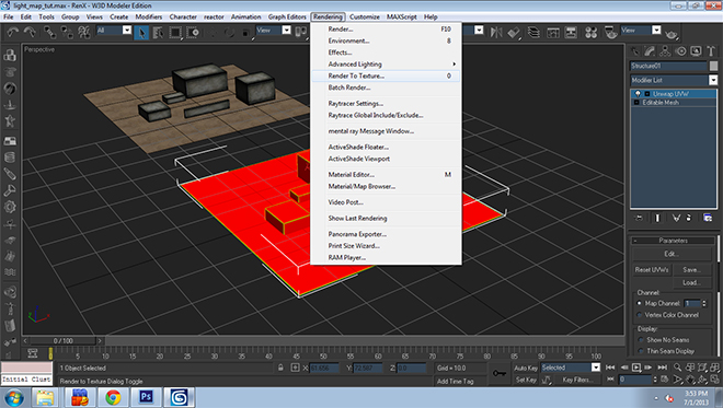
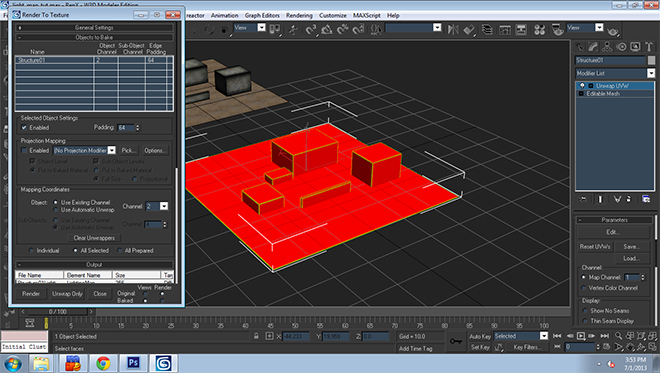
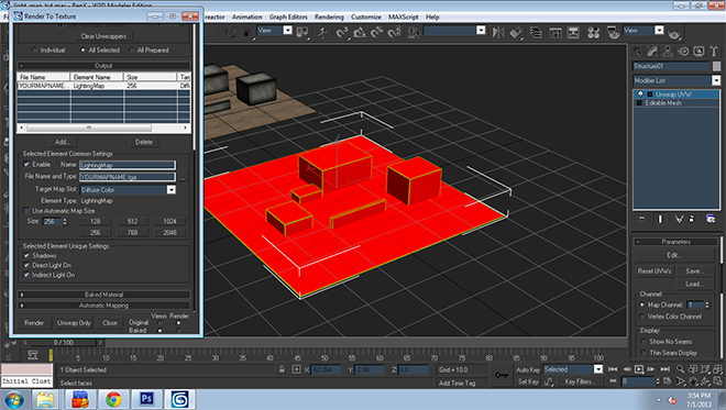
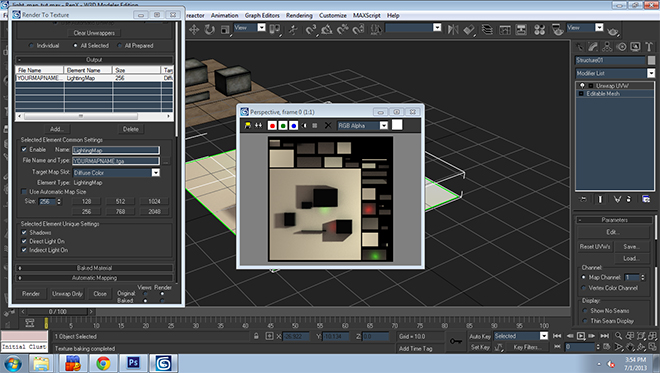
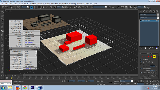
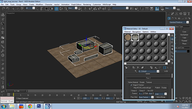
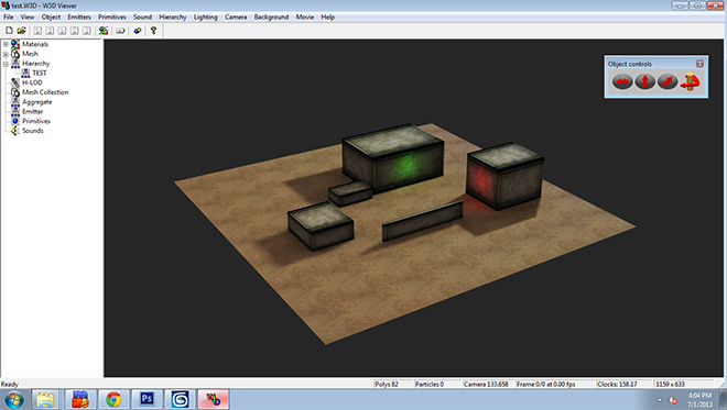
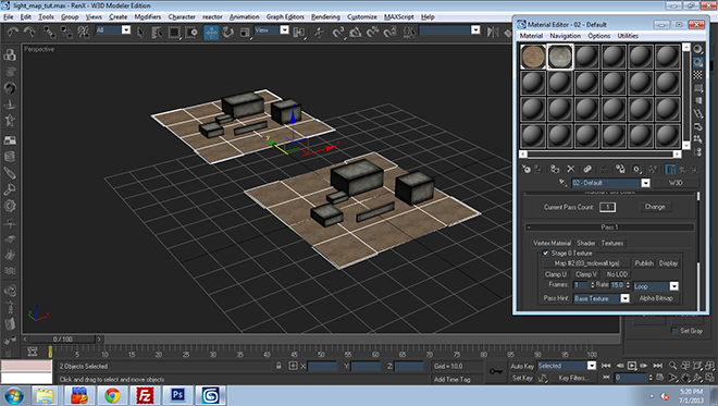
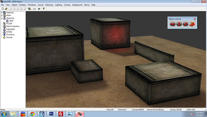
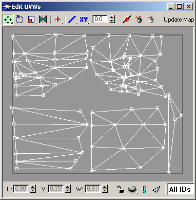
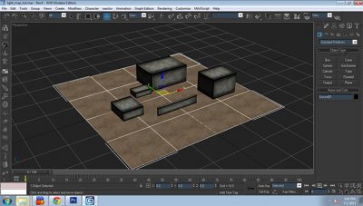
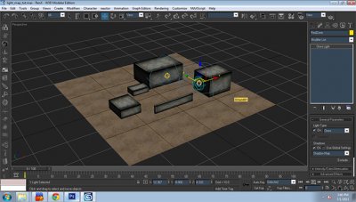
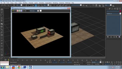
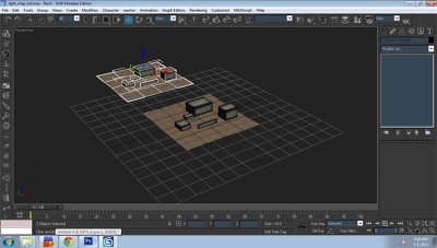
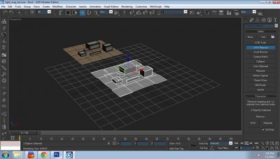
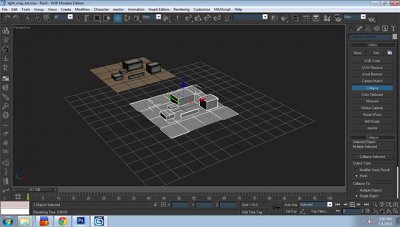
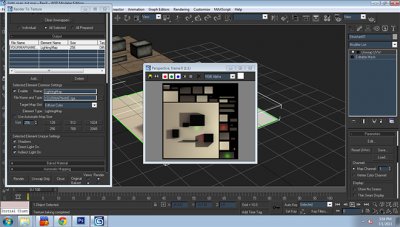
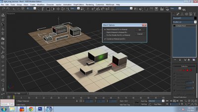
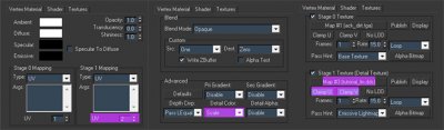
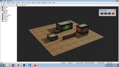
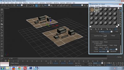
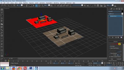
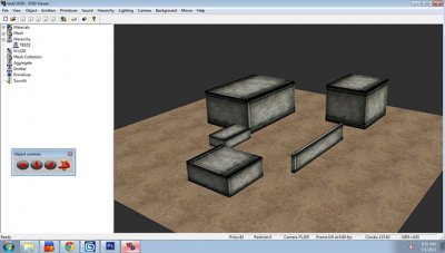
I have finally gotten around to creating a simple tutorial on how to get lighting effects from 3DSMax 8 into Renegade, Some would call this "lightmapping" when using this and some other tools TT have developed you too can get professional looking shadows, lighting effects... just one thing i should mention, this method is not dynamic lighting, but rather static baked in lighting Let's begin Open your completed level, textures are optional, but recommended that the level be completely textured before starting the process. Just easier to render and see the effect the lighting will have on the level Here I have placed some lights and other atmosphere effects to the scene. Let's render [F9] the scene and check out how the lighting looks, Everything looks fine, When you happy with the final product move on to the next step. **Remember to render often to check for lighting errors or glitches be sure to look at all surfaces etc.. Now that our lights are done, lets hide them and just keep the terrain I want to lightmap visible, First thing you want to do is clone all the terrain pieces you wish to apply the lighting to... In my case, it is the concrete boxes and ground. [Right Click > Clone] Now both pieces are cloned simply move them to the side, Leave it there for now, we will work on that in a bit.. As you can see I've moved mine a bit off from center. Now select the original two pieces and remove the materials from them [utilities Tab> UVW Remove>Materials Make sure "Set Gray" is checked] With the materials off the original meshes, we need to combine them for the lightmap. [utilities>Collapse>Collapse Selected] This will make the pieces into one mesh. Now that it is one mesh, we need to apply a UVW unwrap, Select the mesh [Modifiers>UV Coordinates>Unwrap UVW] Now that it has applied a UV unwrap we need to flatten all faces for the lighting information. ** Before moving on set the "Map Channel" to 2, we will need to remember this for later Under "Selection Modes" click on the third button to the left "Face Sub-object Mode" then select all faces in the scene [Ctrl+A] to select all, then we need to flatten, [Mapping>Flatten Mapping]. Once that is done just use the defaults that are displayed on my screenshot. Click "Ok" when done. The modifier should auto-flatten to something similiar to what i got pictured above. Once that is done, move on to the next step. Now we need to render the lighting information to a texture, [Rendering>Render to Texture] This will provide a pop-up of the settings of the texture we will render, Set the Padding to 64, Object should "Use existing Channel" then set the channel to 2, we set this channel from earlier... Continue down to "Add" button, Click on it and select "Lightingmap" after it will provide you with the ability to change the file name and type of the texture output [To change output location click on the " ... " ] **For lightmaps I tend to make them DDS with DXT-1 settings, and Use a 256x256 size Once you are happy with file name and output location press "Render", You should see a pop up with the lightmap texture, something like my lightmap pictured above. Once rendered close the pop up windows Now the lightmap texture is applied to the original mesh, At this point we need to detach the single mesh back into the orginal two pieces we started with.. [Right-Click on the mesh>Detach with the element tool] Once complete move on to the next step. Now this is where the cloned copy of the original comes into play, We need to attach the cloned pieces to the lightmapped pieces. Ground>Ground, Concrete Boxes>Concrete Boxes... Once you attach the cloned copy to the lightmap meshes a pop up will appear [Pictured above] leave those default settings and press Ok. Now that the pieces are attached together we need to re-apply the materials over the meshes, Once complete move to next step Now the two pieces are retextured we need to get rid of the cloned mesh we made earlier [Mine was the top one] just make the mesh editable and select and delete the cloned mesh [Pictured above] We are left with the one piece, Now we need to apply the lightmap texture we made earlier to the materials of the Ground and Concrete Boxes.. Go into the material editor [ M ] and apply the next step settings to the materials. Vertex Tab, Stage 1 Mapping should be set to 2 Shader Tab, Pri-Gradient set to "Disable", Detail Color to "Scale" Textures Tab, Check Stage 1 Texture, And place the Lightmap texture you output earlier here, Click on "Clamp U" and "Clamp V" Once completed close material editor and Export your scene into a W3D Once all is complete and lightmap textures are applied to the mesh/meshes.. You will need to add a user defined parameter.. Right click, goto properties and goto User Defined tab... There you will see a text box add the line [ Prelit=true ] - everything in between the brackets.. And apply this line to all lightmapped mesh.. This is so that the Renegade vertex lighting system ignores these pre-baked light meshes Here is my completed level with Lightmap applied in W3D Viewer... Enjoy! and experiment!! UPDATE: There maybe some possible issues that result from using this method Alpha blended materials will break once "Pri-Gradient" is set to disable. To fix you will need to set to "Modulate" for any mesh that is lightmapped and has alpha blending. Tree, Shrub etc. Shadows not displaying properly in render or lightmap, You will need to follow this Alpha material tutorial for proper display of alpha enabled textures. This is what the model looks like without a lightmap texture and using default vertex lighting instead Hope you guys learned a bit from this... you can now go and create some cool looking levels with this method of lightmapping I've provided for you...It can get very complex for larger, more detailed levels, so you will need to dedicate quite sometime to do it right! I've only covered the basics on this tutorial, but I'm sure you guys can experiment and achieve more... Good luck and please feel free to post any questions you might have about Lightmapping in this tutorial thread...


-
Author: Jonwil, Generalcamo Difficulty: 5 Every physics object in Renegade has a collision group type that describes which other collision types it can collide with. Note that this has nothing to do with the W3D collision settings (physical, projectile, vis, camera, vehicle) that you set in gmax/3ds max. Collision types Scripts 4.x adds a number of new collision group types for various features including boats, subs, hover units, amphibious units and underground units. The full list of collision types (and the in-game numbers that represent them) is: Default = 0 Uncollideable = 1 Terrain Only = 2 Bullet = 3 Terrain and Bullet = 4 Bullet Only = 5 Soldier = 6 Soldier Ghost = 7 C4 = 8 Underground = 9 Soldier Only = 10 Soldier Bullet = 11 Terrain = 15 Water Surface = 16 Water Edge Block = 17 Water Edge Allow = 18 Beach Edge = 19 Naval Unit = 20 Beaching Unit = 21 Hover Unit = 22 Amphibious Unit = 23 Amphibious Unit Floor = 24 This image shows what collision types each collision type can collide with: Note that you can put any collision type on any object e.g. you aren't restricted to using C4 on just C4 objects. The names just indicate their intended purpose. Default preset collisions Terrain always has a collision type of "Terrain". Tiles by default have a collision type of "Terrain" by default but can be changed using the drop-down list in leveledit Objects (i.e. the stuff under "object" in leveledit) can have the script SH_CustomCollisionGroup added that will let you set the collision group using the numbers in the list above By default beacons will have a collision group type of "Terrain and Bullet" C4 will have a collision group type of "C4" Cinematic objects will have a collision group type of "Terrain" Powerups will have a collision group type of "Terrain" or possibly "Uncollideable" (I cant tell from the code which it is, seems to depend on whether its pre-placed in LE or spawned by a script/spawner) Special Effects objects will have a collision group type of "Uncollideable" Soldiers can have various collision groups at runtime depending on their state so using SH_CustomCollisionGroup on a soldier object will not work All objects not otherwise mentioned get collision type "default" For programmers Example from TS: Reborn This next part will describe how things are set up for amphibious and hover units in Tiberian Sun Reborn. Firstly, you need to create the vehicles. GDI Amphibious APC The only special thing you need for the amphibious unit (which is designed to be unit that drives along the ground but appears to be "floating" when in the water) is a copy of SH_CustomCollisionGroup on the vehicle with the value set to 23 (aka "Amphibious Unit") GDI Hover MLRS For hover units (which is for anything designed to travel on top of water and "hover"), you need a copy of SH_CustomCollisionGroup on the vehicle with the value set to 22 (aka "hover unit"). You will probably also want to make the wheel bones and such of your vehicle invisible so it appears to be hovering (The Hover MRLS in Reborn is set up as a tracked vehicle which seems to work best for hover vehicles rather than a wheeled vehicle) Hidden mesh for hovering -Next up you need special geometry on the map to make things work correctly. Firstly create a mesh (in a separate w3d file from the main terrain) for the "water surface" (this is what hover units will drive on top of). This shouldn't be the actual water surface with the texturing on it. It should have flags set to "hidden" and "physical collision" and nothing else. -Export this as "terrain" in gmax/max. Create a tile in leveledit and assign this mesh. It needs to be StaticPhys and needs to have IsNonOccluder ticked, Collision Group set to "water surface" and "visibility mode" left at "default" -Then place your tile on the map like you would with any other tile. Hidden mesh for the Amphibious APC Next up you need to create another similar mesh for the "Amphibious Unit Floor". This is what the amphibious unit will drive on when in the water (so it should be placed such that the vehicle appears to be floating on the water surface when its driving on it, below the water surface) It should be created just like the "Water Surface" mesh above with the same flags and settings except that it should have Collision Group set to "amphibious unit floor". Note that it is the size/position of the vehicle's Worldbox (which for vehicles has Physical collision ticked), not the geometry itself (which doesn't have Physical collision ticked) that determines how low or high the vehicle rides. For example, the Reborn Amphibious APC has a larger worldbox with more worldbox underneath the vehicle than usual so that when it drives on the "amphibious unit floor" it will achieve the desired height so it appears to be floating on the top of the water. The boats in APB (including the naval transport) have part of their structure (the nit that is underwater) sticking out from below their worldboxes so that when they ride on the "water surface" mesh, part of the geometry sits underneath the water. The submarines in APB have any part that is visible above the water when its surfaced to be protruding above the worldbox (as the water surface will act as a "lid" and keep the worldbox from moving past it) Generic naval unit setup The vehicles Ok, now for the tutorial on naval units. Other than the aforementioned worldbox changes, they are just like any other vehicle. The boats (including naval transports) are set up as tracked vehicles (with invisible wheels). The submarines need to be set up as VTOL vehicles so the can move up and down in the water. The only other setting required is to set the "type" as appropriate (either Boat or Sub depending on what you are making). Everything else is as normal for vehicles. As for scripts, both boats and subs require SH_CustomCollisionGroup with a setting of 20 aka "naval unit". Units that can come onto the beach but not onto land more generally (i.e. naval transports) need a setting of 21 aka "beaching unit". The naval-colliding meshes For the water surface in the naval logic, you need to make the actual visible water surface a separate mesh. You need 2 meshes: One facing up for the top surface (which will dictate how low into the water boats will go) One facing down for the bottom surface (which will dictate how high up subs will go) and is what people in submarines see when they are underwater. They need "physical" collision ticked and nothing else (technically they dont NEED to be 2 separate meshes but it should be totally fine to have them separate). Export them as terrain. In LevelEdit, you need to make this as a tile with StaticPhys, "IsNonOccluder" ticked, "water surface" collision and "default" visibility mode and place it in your level. Blockers Next up, you need a blocker around the edge of the water (this will limit where naval vehicles can go, so they won't leave the water and roll around on the normal ground). This should also be "physical" collision only and should be hidden so it cant be seen. In-game, it's the same as the water surface (StaticPhys etc) except that it needs either collision group: "water edge (allow)" (if you want to allow soldiers and normal vehicles into the water) or "water edge (block)" (if you want to block soldiers and normal vehicles from entering the water) Finally, if you have any vehicles with "beaching unit" set on them, you need another blocker further in (just like the water edge) with "beach edge" collision group. This concludes the tutorial on collision detection and how to use it to build boats, submarines, naval transports, amphibious units and hover units. Anyone with questions on all this stuff (or if you are having problems getting it working), feel free to post here or hit me up on IRC/IM.
-
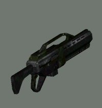
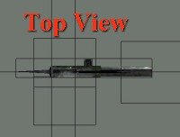
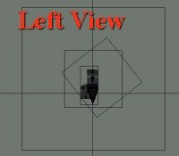
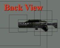
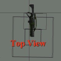
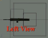
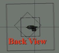
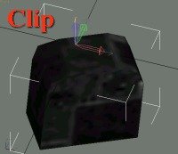
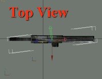
Author: Läubi Skill level: 5 Posted on October 15, 2002, by Abjab at the Westwood Forums Edited, reformated and images added by Läubi on June 4, 2003 [edit: I have reformated the tutorial as well as adding some comments with knowledge that was found out later and things I have found out myself. Additives are marked with a red `edit` plus a number -Läubi ] Ok I know allot of you people have been trying to figure out how to create your weapons so they are correctly positioned and oriented depending on if its viewed in 1st or 3rd person or if its on the character`s back. Well I`ll try to make it easy to understand. First you need 3 individual models for the weapon. it`s always a good idea to use same name convention WW uses for their models, I`ll use the auto-rifle weapon for the example. [edit1: If you do this you can use the reloadanimation and handposition of the WS weapon, if you do not find a weapon that fits your needed handpostion/reload animation you can create your own one for this see the Handposition Tutorial] Weapon models for 3rd person view are named like this: w_rifl.w3d (where rifl is your weapon name) Weapon models for when the gun is on the character`s back are named like this: w_rifl_b.w3d Weapon models for 1st person view are named like this: f_gm_rifl.w3d 3rd person weapon models: All characters have a "gun bone" that tells renegade which hand does hold the gun. the weapon`s pivot point is positioned at this "gun bone" position. In other words, once you have created your weapon mesh, move its pivot where you want the hand to be. You fix the style that the character should hold the gun in Level Editor i.e.: Shoulder: uses both hands (second hand position is set automatically by Renegade) Pistol: uses one hand etc... [edit2: This is only autosetup for 3rd Person view! For 1st Person view see edit1] Now the weapon and its pivot needs to be correctly oriented in RenX: Weapon Orientation: Viewing from top, the weapon should be pointing to the right, and the top side of the weapon is facing you. File: w_rifl.gmax/w3d Pivots Axes: X is pointing to the front of the gun (right in top view) Y is pointing to the top side of the gun (pointing at you in top view) Z is pointing to the right side of the gun (down in top view) Weapons Bones: MuzzleA0, A1: position at which bullets are fired, muzzle bones pivots axes are oriented the same way the weapon`s pivot is. eject: position at which shells exits, its pivot`s Z axis is pointing to the back of the gun and its pivot`s X or Y determines which way the shell exits (I think X does) [edit3: As far as I know the eject bone is obsolent for 3rd person view because Renegade do not show the outcoming clip in 3rd Person view] Origin: use world axes coordinate, positioned a little back of the weapon`s pivot (approximately at elbow`s position) [edit4: from my experience this affects the position of the elbow if you use an twohanded mode like shoulder in Leveledit as mentionted before.] If you use a muzzle flash aggregate, link it to the muzzle just like for vehicles. 1st person weapon models: For 1st person view, you can use the same model, or create a simplified version of it with details only in the viewable parts of the gun. Also, for 1st person view, you have to create a magazine mesh for the reload anim. [edit5: Better use a simpler version of the weapon for 3rd Person view than for 1st Peron view!] Like for 3rd person view, the weapon`s pivot position determines where the hand should hold the gun. Weapon Orientation: Orientation of the weapon for first person view is different then the 3rd person. Viewing from top, the weapon should be pointing down, its right side facing you. File: f_gm_rifl.gmax/w3d Weapon Pivot axes: X is pointing to the top side of the gun (right in top view) Y is pointing to the back side of the gun (up in top view) Z is pointing to the right side of the gun (pointing at you in top view) Magazine Pivot axes and position: X is pointing to the right side of the gun (pointing at you in top view) Y is pointing to the back side of the gun (up in top view) Z is pointing to the top side of the gun (right in top view) The pivot of the magazine is positioned at the top of the magazine mesh (pivot`s Z max), back most of the magazine (pivot`s Y max) and left most of the weapon side (pivot`s X axis). The magazine mesh itself is positioned wherever you want it to be on the gun. Name the magazine: f_cm_rifl (where rifl matches your weapon`s name) Weapons Bones: MuzzleA0, A1: for 1st person view, muzzle bone uses a different pivot orientation, X points direction of bullets (down in top view) Y is pointing to the right side of the gun (pointing at you in top view) Z is pointing to the top side of the gun (right in top view) eject: eject bone`s pivot orientation is also different from 3rd person view, X should be pointing direction of shells to exit (right, up 45 degree) Y is pointing to the back side of the weapon (up in top view) Z is pointing right, down (45 degree) Origin: Origin might be determining how far the gun is from the camera, in the auto-rifle w3d, it is centred to the weapon`s pivot position, aligned with world coordinates. [edit6: in fact this is the bone that gets attached to the gunbone of the character. How far the weapon is away from your Character is setup in Leveledit.] Back weapon models: This is the model used when on the back of the character, there is no bones for this model. Only the mesh itself and its origin. Weapon orientation: Same orientation of the 3rd person model. Viewing from top, the weapon should be pointing to the right, and the top side of the weapon is facing you. File: w_rifl_b.gmax/w3d Weapon`s pivot orientation: Since it is on the character`s back and that the weapon is not straight on the back, the pivot axes determines the angle of the weapon on the character`s back. Since this would be hard to explain, here`s the XYZ rotation in absolute world coordinates for the auto-rifle. To set your weapon`s pivot rotation simply click on the "affect pivot only" in the hierarchy tab, then right click on the rotate tool and type this in absolute world X,Y,Z: X: -0.9516 Y: -7.6463 Z: 7.3055 Weapon`s pivot is centred with the weapon Origin is positioned at the same point where the hand should hold the gun in 3rd person view. (weapon`s pivot point of 3rd view model) Origin using world axes coordinate as always. [edit7: I dunno what Ajab means with that, but you just need to center the orgin to the weapon.] Finish: Ok that`s it for the RenX part, now all the rest is set in Level Edit, try messing around with settings until you get the results you wish. [edit8: You can now start with doing your own handposition and reloadanimation if you want one. For informations see edit1] Hope that helped, Abjab [edit9: I hope that too, and I hope my notes help you to better understand this Tutorial. Have fun with the Tutorial and modding for Renegade] You can download the files I used to create the screenshots here. This is just the standard rifle imported into Gmax, I have corrected just the textures a bit and set the bones so they are not visible after export.
-
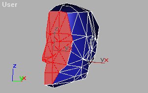
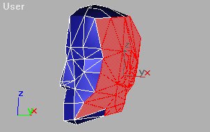
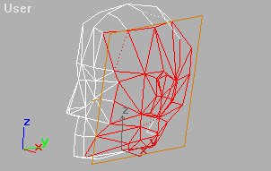
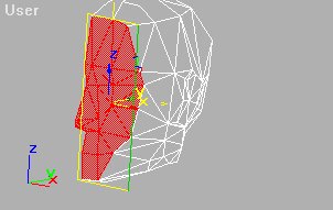
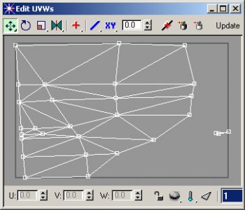
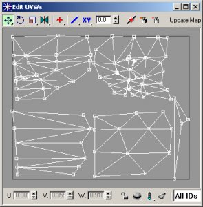
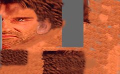
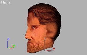
 Author: MadTone Skill level: 5 A brief summary of the steps Editable Mesh - Select sets of polygons andassign an ID number to each set. Apply a Mesh Select modifier, use it at Sub-Object level to select Polygons by their ID number. Do not turn Sub-Object off. Apply a UVW Map modifier to the set of Polygons - Planar Map only. Repeat steps 2 and 3 (apply new Mesh Select, do not try to use the previous one). Apply a Mesh Select modifier. Do not turn Sub-Object on. Apply Unwrap UVW modifier. Edit (in UVW Unwrap) select one set of face ID`s at a time and layout the poly`s so that they are separate from each other. Show all ID`s Take a screengrab of the UVW Unwrap Edit window. Paint on the screengrab and save as a .jpg, .tif, or .tga. From the Asset Manager, drag and drop the saved painting to the mesh model. Assigning the Polygon ID numbers Imagine that your mesh was layed out flat, that`s what the UVW Unwrap modifier does. This tutorial will illustrate how to texture the head mesh shown in the following picture : 1. Select the front of the head at Sub-Object Polygon level. Press F2 to shade the selected faces in red. 2. Type in number 1 in the Material ID and press enter. Doing this will assign the number 1 to the selected polygons. 3. Select another set of polygons. 4. Continue selecting polygons and assigning ID numbers. Color Coding the Model Apply a Multi-Sub Object material to the mesh so that you can see if all of the ID numbers are assigned correctly. This material is not used with the final texture, so this is just a temporary material to check where the ID`s are. Make sure that you turn Sub-Object off from the Modify command panel before you do this. Turn Sub-Object off in the Modify command panel. Open the Material Editor. Click the Standard button and choose Multi/Sub-Object from the list. Choose Keep or Discard the original material. It doesn`t matter which, you haven`t changed it. Drag and drop the Sample Sphere on to the mesh. Change the color panels at the right of the Multi/Sub-Object material. You should see parts of the mesh changing color. Look at your model. If any of the colors are in the wrong place, go back to Editable Mesh Sub-Object level and assign those ID`s to the correct numbers. Tip: In Editable Mesh at the Polygon level, click a Polygon and the ID number of that polygon will show up in the Material ID panel. Mapping Mapping a mesh `pins` vertices of the mesh to positions on a picture. This is similar to a dressmaker laying out a pattern onto fabric. In this sequence, you select parts of the mesh and apply mapping to each of the parts. Do the following for each set of ID numbers that you assigned to the model. Turn off Sub-Object for the Editable Mesh. Apply the Mesh Select Modifier. Turn on Sub-Object and choose Polygon level. Click the Select by ID button, polygons with the number that is in the ID panel will become selected. Don`t turn Sub-Object off. Apply a UVW Map modifier. Use Planar, you may need to rotate and re-size the UVW Map Gizmo. Examples: UVW Unwrap Apply a Mesh Select modifier but don`t turn Sub-Object level on. Do this to return the selection level back to Object level. (if you look at the last UVW Map in the white panel it has a star next to the name. The star shows that the modifier has been applied to a sub part of the mesh.& Apply the Unwrap UVW Modifier. Click the Edit button, then open the Face ID drop down list at the bottom of the dialog. Choose just one number to display the faces with that ID number. The name Faces might be confusing, these are actually the Polygon ID numbers that you assigned at the beginning of this tutorial. So what you are doing is displaying only one set of ID numbers at a time. This screenshot of Polygon ID numbers shows a problem with some extra vertices at the right of the picture. These are faces that weren`t assigned the correct number. You will need to find out which number the extra vertices should be assigned to, re-assign them and re-map them. Then, you must re-map Polygons number 1 to fix the map. The above picture is what Polygon ID`s number 1 (on our model) looks like. Scale and Arrange the Sets of faces Screengrab the UVW-Map and Assign the Skin The next step is do a screengrab and to paint on the grab. Make this dialog as big as possible. Make a screengrab of this dialog by pressing the PrtScn button on your keyboard. Alternatively, go to www.techsmith.com and download the evaluation version of Snagit, a really good screen/window dialog capture program. You should be able to see which set of polygons are where on your model. If you can, then you can paint on the polygons. Crop the picture so that the dark gray rectangle is the edge of the painting. Save the picture in your favorite format. Good formats include .jpg, .tif, and .tga. The next step is simple but important. Open the Asset Manager and find the picture that you painted. Click and drag the picture onto the model. The result should show the picture fits perfectly according to the mapping and Polygon ID`s that you set. Finally It is recommended, but not essential that you collapse your object back to an Editable Mesh. It is recommended because most game engines require the UVW Mapping to be built in to the object. Not many game engines will understand the Mesh Select and UVW Mapping if you leave it on an object. The object will retain the mapping that you applied. To collapse the object click Edit Stack in the Modify command panel, then choose the Collapse All option.
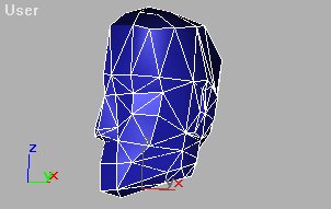


-
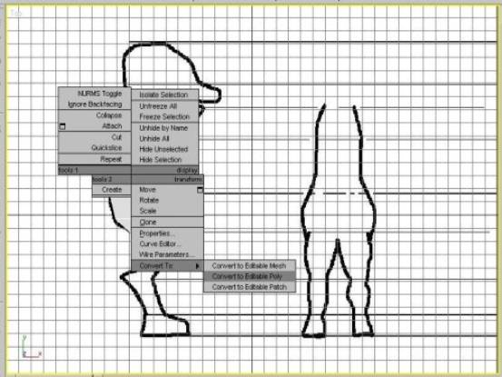
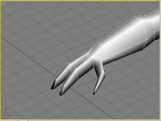
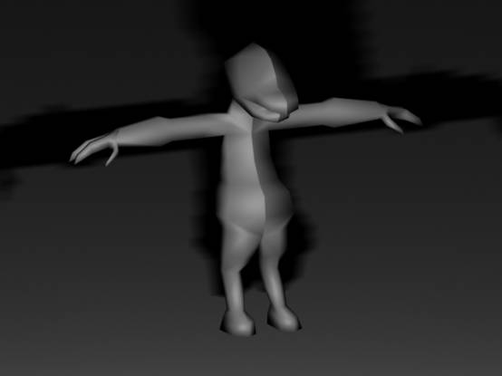
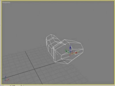
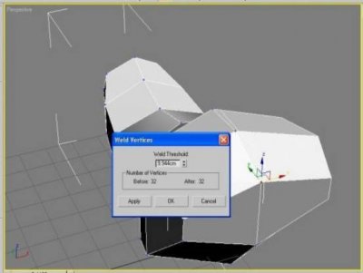
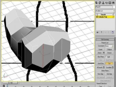
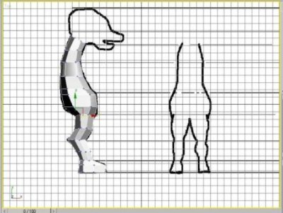
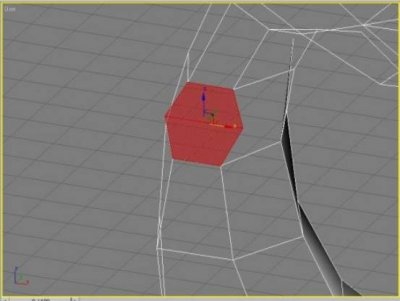
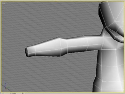
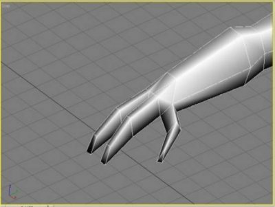
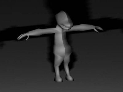
Author: PsycoArmy Skill level: 5 In this tutorial you will find how to build a character model form a simple plane. I will show you how to use Edit poly tool. You will also learn to model using SHIFT + DRAG on EDGE tool to create that shapes you need to start. In this tutorial I will show you how to use CUT tool found in EDGE section, this tool can come in handy in lots of places, also use EXTRUDE to get some of the shapes. This tutorial is done in 3d Studio Max so if you are using something such as GMAX this tutorial should still work fine except for 1 or 2 steps, I will also be showing you how to WELD too, which can be found in VERTEX menu. Here we go. ------------------------- For models you should always try to keep the model in Squares, using triangles is all right with low poly. The purpose of this tutorial is to teach some basic character modelling skills; the methods can also be used in modelling of all sorts of thing not just characters. When modelling a character it is good to use concept even like the one I use here. Create a plane with 1 by 1 sides. Place the plane on the area where you want to start. Right click on your plane and click CONVERT TO > CONVERT TO EDITABLE POLY. Once you have done so u can use VERTEX on the right menu to fit your plane in better. Now we can make the 2D shape of the character. Select EDGE in EDIT POLY menu, click on the first edge you wish to make another segment from, once its selected hold down shift and then move it to the direction you want the segment to go. Continue this until you have the main body part filled like the picture below. Now we are going to use CUT to get the poly amount we need. CUT can be found in EDGE selection down the menu. Using cut is very simple, you just first click cut on the menu, and click the edge where you want to start the new line for the model. Just continue the line through. Now when you have the poly amount you think you need for your model change it to perspective but keep the part selected you want to go out to make the side view. Move it to the side or what ever view your using. Now we can start modelling the 3d shape more. Its good to change it to VERTEX for this one. Move all the VERTEX to make the shape you want it to look like form the front. You can always change position of different VERTEX to make your shapes more to your liking. Always remember that its a 3d environment and you will always need to adjust bits. Now we are going to learn to close off open bits and then model the legs. Use EDGE and SHIFT + DRAG technique here and move it to a good location, use VERTEX too if you need to. Now we are going to weld the VERTEX. Make sure VERTEX is selected, now select the 2 VERTEX you want to WELD. Now WELD can be found in VERTEX, It might be down in the menu a bit in GMAX (not sure). But dont click WELD just yet. Click the little square thing next to the WELD button. This will give you an amount you can WELD to, but seeing you have wot u want to WELD selected just pump it up (you can do this by holding down on the up button and dragging up.) until the 2 VERTEX connect. Remember the WELD button by itself should work fine; just the little square thing gives you more control. Now we will model the legs (in this part I dont keep it squares, I suggest when you do it you keep it all mostly squares, a good 90% of the model should be squares.). Now just cut it form where you want the leg to start, CUT it to how many sides you want it to have. Now just move it to the basic shape it will start as. Now we will use EXTRUDE, first step is to select the POLYGON menu in EDIT POLY. Now select all the shape you want to start the leg from. Now find EXTRUDE and you can use the box next to it for this one, just keep extruding until you have as much poly as you need to make the leg. Now use VERTEX to shape the leg in its front and side views. Perspective is also a good view to use to get the shape right. PLACE PROPER IMAGE HERE (edit it properly ) Im not going to post any pics for this part because its exactly the same for the body and legs. We will be making a shitty headJ; first I just did it as a plane for the basic head shape and just used all the first few steps to get the shapes. Then I used extrude to get the shape for the mouth. I jut used my concept to match it up at the side. I also used weld to attach the head to the body. You can attach the 2 objects by using the EDIT POLY menu where it says ATTACH, just select the first object yo want to attach and then select ATTACH in EDIT POLY and then click what you want to attach it to. ARMS are what we are making now. First make the area you want the arms to start from just like the legs. Now just EXTRUDE and shape it until you have you arm done. Now to make the fingers just use all the past steps, use CUT, EXTRUDE, VERTEX all of the stuff I have mentioned to get the hands you want. It`s good to do one side then clone it and mirror it. Once its mirrored you can weld both sides together, this can get rid of any chance of there being any gap in the centre. I did this model very quickly just for this tutorial, and here was the final I got from it, if you want it you can have itJ. Tutorial Created By Psycoarmy Edited By Genocide
-
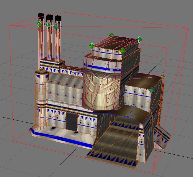
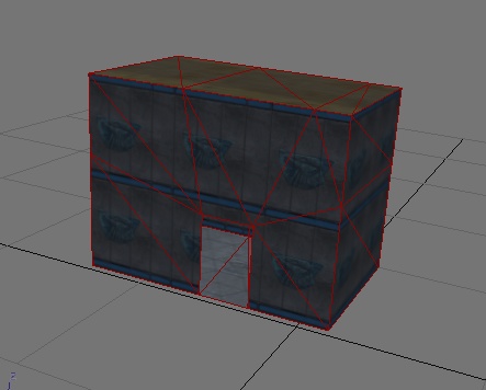
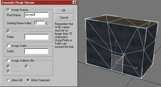
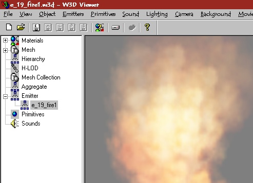
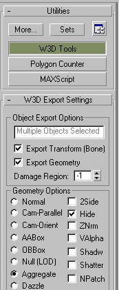
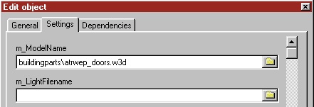
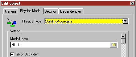
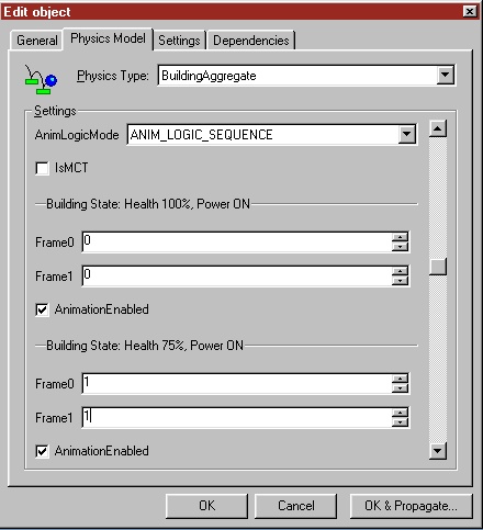
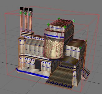
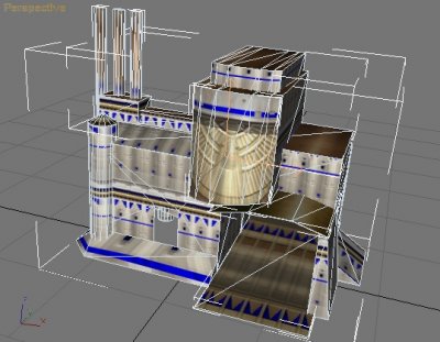
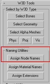
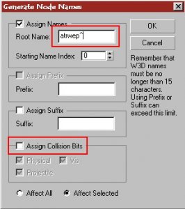
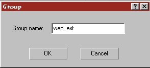
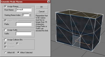
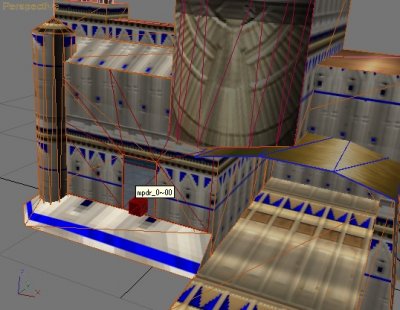
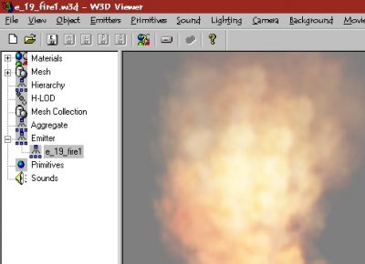
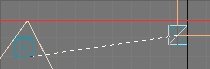
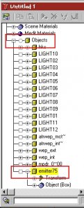
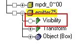
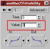
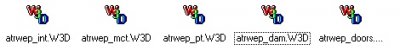
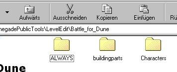
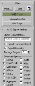
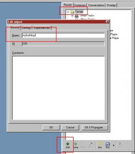
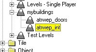
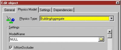
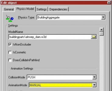
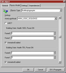
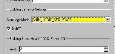
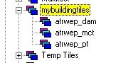
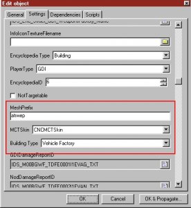
Author: Läubi Skill level: 5 A Step by Step to create a full functional building like the Westwood ones. Important!! Read this tutorial carefully. If something didn`t work as you have expected it, check the coresponding part of the tutorial if you have not miss a thing. 1. First of all, of course you need you building. Mine I use for this tutorial is the Atreides Weaponfactory for the Battle for Dune Mod ( laeubi.de/bfd ) It is important that you move your whole building to the center of RenX. You also should already have setup all collision settings. 2. Now select all the meshes that are part of the EXTERIOR. This should be all parts of the exterior of the bulding, excluding any emitters, animations or doors. Then goto the W3D-Tools --> Assign Node Names: In the following dialog uncheck/check the Options you see on the screen below, enter at the Root Name: entry a short name, e.g. atrwep (atreides weponfactory) followed by a ^. You should write this down. because youll need that later, I`ll refer to this name as the Meshprefix later. The Meshprefix should NOT exceed 6 characters. 3. Congratulation you have now created a buildings exterior. Now goto Group --> Group and enter a name (e.g. wep_ext) 4. Now hide your ExteriorGroup and unhide all parts of the interior, again excluding any emitters, animations or doors. Again select all meshes and open the same dialog as for the interior. Enter the Meshprefix followed by a #. Again Group this and name it for example wep_int: 5. Now we will add the doors, emitters as well as animate them for the later use. If you have already done this, you can just skip this part. For the doors I`ll use the standard Rengade MP ones, but of course you can make your own ones, you find a tutorial at: Door tutorial how to set up those. As you can see, I have unhidden the Ext/Int-Group to better align things. For the doors you need the name of the preset of the door, the standard Rengade doors name is `mpdr_0` create a box 1x1x1 at the topview, and place it at the location where the door should be placed, name the box : mpdr_0~ (or the name your door-preset has in Leveledit + a ~ ) add a 00 after the ~ for the first, a 01 for the second and so on. When you have placed all doors, group the doors e.g. as wep_doors. When you are done with the doors, you need some damage emitters. You can make your own with W3D-Editor or use Renegade ones, extract them with XCC_Mixer you can identify them by the leading e_ (e.g. e_19fire1.w3d). For all Emitters you should extract (or download) the e_master01.tga so you can see the emitter effects: Now create three boxes (1x1x1) named: emitter0, emitter25, emitter50, emitter75. I will refer to this as the `DamageBox`. After that, create 1x1x1 boxes named like the emitter file (without the w3d) that should be displayed later, in this case e_fire1. I will refer to this as `EmitterBox`. IMPORTANT: Never just rename the emitter file!! You must edit the name in w3d-Viewer and re-export it or the file will not be loaded or even crash Renegade!!! Now link the EmitterBox to the DamageBox emitter75 if this emitter should be showed up at the state for when the building is 25% damaged, emitter50 for half damged, emitter25 when the bulding is damaged by 75% and emitter0 when the building is detroyed. For this use the Link tool and klick and drag from your EmitterBox to your DamageBox (The damage box will flash for about 2 sek when this is done succesfull). Then place all around your building emitters or objects that should be displayed at the different states and link them to the coresponding DamageBox. I recommend to save your work now if you have not done this before!! 6. Now we must make an animation, so Renegade later know what parts must be showed at the damage states. For that you should reopen RenX, because the `Trackview` that we will need often conflicts with the RenegadeMaterialEditor for Gmax, restarting RenX solves the problem. Open now the `Trackview`: On the Trackview browse to Objects --> emitter75: Add a visibility track by clicking the eye icon that will add a new option to your Object: Click on the new option and add via the at frame 1, 2 and 3 a new key. Rightklick the first key and change the value to 0 (invisible) Now change this also for key2. The trird key must not be changed and should stay at value 1 (visible) Repeat this process for all other DamageBoxes, but switch the keys to the following: emitter50 frame 1,4,5 emitter25 frame 1,6,7 emitter0 frame 1,8,9 When you have done this, group all DamgeBoxed and the EmitterBoxes e.G wep_emitter 7. Now we will prepare the PT and the MCT (This is optional) Your PT`s and MCT can have also animations like the damage emitters. For the PT`s you might want to add animations for a powerless building like westwood does. for thsi jsut create four more emitter boxes( emitter0p, emitter25p and so on) and count up the last frame by one for each state liek you have seen in Section 6. Select all MCT Meshes and use the naming tool that is described in Section 2, and use as a basename the meshprefix#mct (e.g. atrwep#mct). repeat this for the PT`s also but use meshprefix#pt here (e.g. atrwep#pt) Group all your PT`s and the MCT to a seperate group, e.g. wep_pct and wep_mct 8. Exporting time. Now you must export all parts for the use in Leveledit. Export: * the Interior Group as mesprefix_int (Renegade Terrain) * the Doors Group as meshprefix_doors (Renegade Terrain) * the Damage and Emitter as meshprefix_dam (Hirachy Animated Model) * The MCT Group as meshprefix_mct (Hirachy Animated Model) * The PT Group as meshprefix_pt (Hirachy Animated Model) In my example I`ll get 5 files: atrwep_int.w3d, atrwep_doors.w3d, atrwep_dam.w3d, atrwep_mct.w3d, atrwep_pt.w3d Copy all these files into Your modfolder if you have not done this already, a seperate folder e. g. buildingparts would be a nice idea. 9. Setup your exterior mesh for use in Maps. You might wonder what will happen to the exterior mesh. We must jsut setup some very simple parts to finish this: create a box from the TOPVIEW (1x1x1) in the EXACT center of Gmax/Renx. Name this box meshprefix_int~, then clone the box (or create a new one) and name it meshprefix_doors~ and so on for all w3d`s you have exportet in part 8. then select all these boxes and activate the [x] Hide and [x]Aggregate w3d option. After that select your ExteriorMesh and these Boxes and group them to for example AtreidesWeponfactory and save your work. You can now Merge this Group into your map(s) like the orginal westwood buildings. 10. Setup everything in Leveledit. Now start the Leveleditor and Load your Modpackage. Goto Terrain-->Add and enter a name, e.g. mybuildings Select this new group and press again add. Enter as name meshprefix_doors (e.g. atrwep_doors) and under the settings tab under m_Modelname select your _doors w3d file. Repeat this part also for the mesprefix_int w3d file, you`ll then has 2 new entry`s: Now change to the Tiles Tab and again press add create a new entry named: mybuildingtiles under the Physics Type select BuildingAggregate. Select this new group and once again press add, enter as name: meshprefix_dam, under the Physics Model be sure that the type is Building Aggregate, change the Model Name to your coresponding w3d file, the AnimationMode to Manual Scroll down to the Building Behavior Settings and change the AnimLogicMode to ANIM_LOGIC_SEQUENCE. The Buidling state for 75% to 1, 1 as showed below, for 50% 2,2 for 25% 3,3 for detroyed 4,4. Repeat this also for the State: Power OFF. After that press OK, again use the add, now enter as name: meshprefix_mct (e.g atrwep_mct), select the needed w3d, setup everything like before, but check the checkbox labled [x] IsMCT. If your MCT also has animation sequences, you must set them up coresponding to your animation as described above. Again add another tile, name it meshprefix_pt, set it up as explained for the MCT, but let the [ ] IsMCT uncheked. Now you have three new entrys in your mybuldingstiles group: 11. Congratulation!!! You are finihed now. Add your BuildingGroup you have created in part 9 to your map via the MERGE command in RenX/Gmax, export it as RenegadeTerrain and enjoy your bulding. One Last Step: To make your building work ingame you have to Clone wia the ADD button one of the Buildingcontrollers, for example mine is a Weponsfactory, so I clone the GDI_Weponsfactory: You can name it whatever you want.... but you must fill in the MESHPREFIX into the coresponding field: Of course you can edit other settings like health in this dialog too,play around abit with these settings Have Fun by detroy all your hard work ingame


-
Author: Hero2112 Skill level: 5
-
5 - Advanced UVW Unwrapping 101 with OWA
moonsense715 posted a topic in Modelling, Unwrapping & Texturing
Author: @OWA Skill level: 5 -
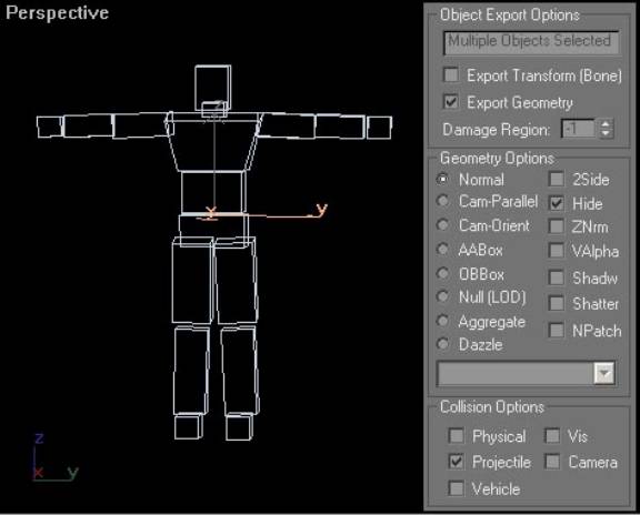
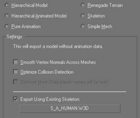
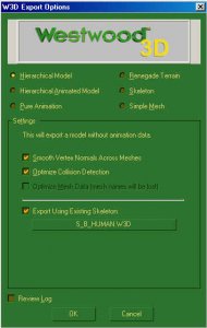
Author: Westwood Studios Skill level: 5 By Greg Hjelstrom Creating a New Character Model To create a new character model for Renegade, you will want to make sure it is compatible with one of the animation sets that come with the game. In order to do this, you need to model your character on the same set of bones that we used to create our characters. Some gmax files can be found in the character examples directory that will allow you to do this. The file named Male.gmax contains the bones for a male character and the Female.gmax file contains the bones for a female character. These files contain several elements that are critical to creating a working character. The Skeleton Below is a picture of the male template with everything except the bones hidden. Remember that for a W3D model, a bone is simply anything in the scene that has the Export Transform option enabled. For a character model, it is important that you observe the following limitations: - For the base pose (frame 0), never move or rotate any of these bones. You may animate them in max to test your character but never change them in the base pose. - You cannot create new bones or remove existing bones or your model will be incompatible with the animations in the game. This means that any meshes you add to the gmax file to create your character must have the Export Transform option disabled. Collision Meshes Characters use two kinds of collision detection in Renegade. There is a single box in the character that is named WorldBox and is used to physically move the character around in the world. This object is flagged to be an AABox (axis-aligned-box) and has physical collision enabled on it. There are also a set of meshes attached to the skeleton that have projectile collision detection enabled. The names of these meshes tell the game engine how to scale the damage applied to a character when a bullet hits them. Below is a screenshot of the projectile collision meshes for the male character and their W3D settings: Notice that all of the projectile collision meshes are marked as hidden and they do not have Export Transform enabled. They are simply hierarchically connected to the bone they are supposed to move with. Modelling your character To create your character model, you can put any number of meshes or skinned meshes into the file. Typically, we used a skinned mesh for the body of each character and a skinned mesh for the head but there is nothing preventing you from using rigid meshes that are hierarchically linked to the bones (like the collision meshes are) to make a more robotic looking character. Characters may use any W3D material settings as well. Read the W3D documentation for more information on how to model and texture your character. Exporting Your Character When you export your character, you need to use the following export options: The key option here is the Export Using Existing Skeleton option. This tells the exporter to make your model use the existing S_A_Human.W3D skeleton (which will work as long as you did not move, add, or delete any bones in your gmax file). The S_A_Human.w3d file is for male characters and the S_B_Human.w3d file is for female characters. Exporting your character in this way ensures that the game will be able to play all of the character animations on your model.