moonsense715
-
Posts
5,440 -
Joined
-
Last visited
-
Days Won
121 -
Donations
60.00 USD
Content Type
Profiles
Forums
Events
Documentation
Bug Tracker
Downloads
Everything posted by moonsense715
-
If you haven't seen it yet it should give you a good understanding how things are unwrapped. Packing is up to you. (Video by One Winged Angel)
-
It's okay. We are a small community here and I do want to support everything w3d related. Even if their servers are empty (for now! )
-
This looks amazing Jerad. Very nice work so far!!!
-
I'd like to try it out though!
-
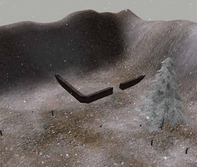
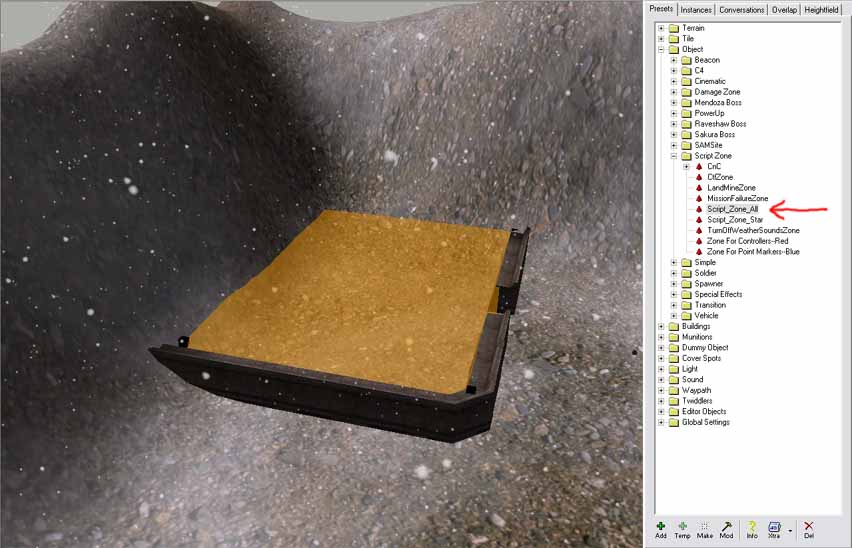
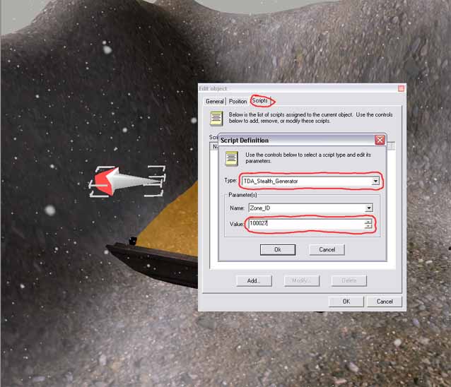
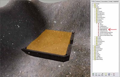
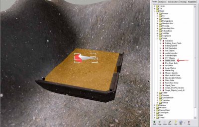
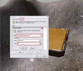
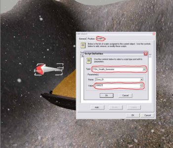
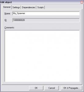
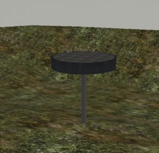
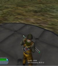
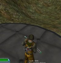
Author: General Havoc Skill level: 1 Getting Started This tutorial will guide you through making a working stealth generator zone on a map. After you have completed this tutorial you should have enough information to add a stealth generator zone to any map. I will guide you through each step of making a stealth generator zone. You may wish to skip some steps if you know what your doing. The stealth generator zone works using a custom script written by Dante that needs to be setup correctly for it to work. 1) Scripts Here is some information about the scripts that are used in this tutorial: TDA_Stealth_Generator_Zone - This script is attached to a scriptzone and defines the area where an object will be turned stealth. This zone will turn infantry and vehicles stealth whilst they are in the zone. The objects uncloak as soon as they exit the zone. There is a side effect to using this script, when the object exits the zone they will have inherited a stealth effect, similar to that of an uncloaked stealth tank or blackhand. TDA_Stealth_Generator - This is the script that powers the stealth generator zone and is attached to another object. The script is normally attached to an invisible static object and then linked to the zone using the zones ID. This script can be attached to other things to give the desired effect. If it`s attached to a vehicle, then when the vehicle is destroyed the zone will no longer make objects stealth. When added to a building controller then when the building gets destroyed the zone gets disabled thus not making objects in the zone stealth anymore. 2) Setting Up The Map Before we add the script to the map you will need to load up your terrain into Level Edit and check that your map is set up correctly and will work in the game. We will be adding the parts for the TDA_Stealth_Generator_Zone script to start with. After you have loaded up your terrain into Level Edit we can start to add some of the required objects. The fist thing you will probably want to do is add an object to indicate where the stealth zone is. You will probably want to do this in the stages of your map making so that people know it will be a stealth zone. I have used walls to show where it is going to be on my test map. This is to tell the player where the stealth zone is because the script zones are invisible in the game. The next step is to add a script zone that will indicate to the script the zone that any object goes within will be turned stealth for the amount of time it remains in the zone. You will find the script zone under Object > Script Zone > Script_Zone_All. Make this object so it appears on the map, move the zone so that it covers the area you wish the object to be turned stealth in. You can size the zone using the back dots in the corners, holding shift will allow you to drag the zone upwards. !t doesn`t have to completely cover the object or area, an it doesn`t need to be as tall as the object your turning stealth, just as long as the object can come into contact with the area. The next step is to add the parts for the TDA_Stealth_Generator script. This script is like a "controller" for the zone. You will need to add an object for this controller to be attached to. See the information about the scripts at the top of the page for more information. If you want the zone to be always active and cannot be destroyed then use the arrow as I have above. If you want to make the zone so it can be disabled then you`ll have to use a building controller or a vehicle depending on what you want to use to disable it. 3) Setting Up The Scripts The last stages are to setup the actual script so that it is linked to everything we have made so far. Go back to the script zone we made earlier and double click it. Then got to the scripts tab and click "add" this will bring up a box similar to the one in the picture below. from the "type" list you should see a list of different scripts, if you don`t see them then you have not installed the scripts into your mod folder correctly, follow the process at the start and check to see if you did everything correctly. From the list of scripts scroll down until you find "TDA_Stealth_Generator_Zone" select that then you should see the same as below. You should see a section with the title "parameters", this is where you select the parameters. As you can see this script only requires one parameter, which is "Player_Type". The "player type" parameter tells the script which team it should activate the stealth for when an object belonging to the specified team enters the zone. 0 is "GDI", 1 is "Nod" and 2 is "Unteamed" or "GDI & Nod". Enter the number in the box according on how you want the zone to work. Click okay and return to the main level. Next double click on the controller, this should be an arrow, a vehicle, or a building controller. It can also be other objects, you`ll understand once you have used it. Go to the scripts tab and "add" script as we did before to bring up the box below. From the list of scripts scroll down until you find "TDA_Stealth_Generator" select that then you should see the same as below. You should see a section with the title "parameters", this is where you select the parameters. As you can see this script only requires one parameter also, which is "Zone_ID". The "Zone_ID" parameter tells the script where the zone to generate the stealth is. This requires you to get the ID form the scriptzone we created earlier, do this by double clicking the object, it should come up with a screen and there should be a box named "ID" with a six digit number in. Type this number into the value box for the parameter. Click okay then your script is set up. 4) Testing Congratulations, you have successfully added a stealth generator zone to your map. You can now save it and test it in renegade. You may need to adjust it if it is not working as it should. Follow each step carefully again if you think you may have messed something up. Good Luck! 5) Credits This tutorial was written by General Havoc (Robert Hunt) I`d like to thank Dante for getting this script working and originally writing the script and may others. Also John Wilson for working on the scripts.dll. Also many thanks to the many people who help on the Westwood Mod Forums. Finally of course Westwood Studios for the excellent series of C&C Games. Let Westwood Live on!
-
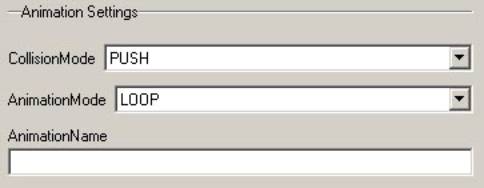
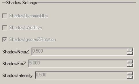
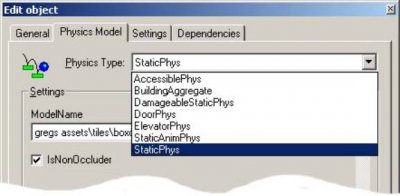
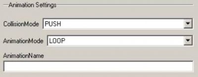
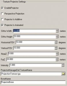
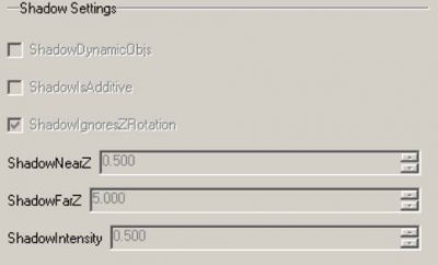
Author: Westwood Studios Skill level: 3 By Greg Hjelstrom Introduction A level for Renegade is composed of static and dynamic objects. This document will give you a brief overview of the types of static objects you can create. Static objects never move and cannot be created or destroyed in game. That being said, you can do a lot of things with animated static objects (including hiding or un-hiding the object, achieving the effect of creation or destruction). In the Renegade level editor, there are two categories of static objects: Terrain and Tiles. These two types are handled significantly differently. Terrain A terrain for Renegade is treated as a collection of individual meshes. A terrain cannot be animated or changed in any way. The bulk of the geometry for any given level is in the form of one or more terrains. Terrains should always be exported with the Renegade Terrain option in the Tiles Tiles are static objects that can animate in various ways. Doors, elevators, damageable objects, and building aggregates are all examples of tiles. The physics model you select when you set the tile up in the editor defines the logic that controls how a tile animates. Below is a list of the physics models available to tiles: StaticPhys An object that uses the StaticPhys physics model is just a static object in the level. This is the simplest type of static object and cannot animate. The only two parameters are the model name and a checkbox indicating whether this object is an occluder. StaticAnimPhys This is a simple animating object. This can be used to make trees that sway, radar dishes that spin, etc. All of the other physics models in this document are derived from StaticAnimPhys and have all of its parameters. Animation Settings: Collision Mode: The most powerful feature of animated tiles is the ability to animate the physically collideable meshes in your model. You can select from several collision modes: none, stop, push, and kill. Probably the most useful of these is the push mode. The push mode will cause the physically collideable meshes in your tile to push the dynamic objects in the game. One limitation must be kept in mind when you use this mode however you may only use translation on meshes that are animating with collision mode push. Elevators (called lifts in other games) simply use the push collision mode on their mesh to move characters and vehicles around. Animation Mode: There are three animation modes: loop, target, and manual. Loop is the most common mode and simply causes the object to play its animation over and over. Target and manual are used when there is other code controlling the animation of this object. Animation Name: Normally, a StaticAnim object will use the animation built into its w3d file (just use the Hierarchical Animated Model option in the exporter). However, if you want to play a different animation on the object, you can specify that animation here. Typically it will be in the fully qualified form: .. For example, if you export an object named MyTree. Then you create a separate animation called WaveAnim, then the full name of the animation will be MyTree.WaveAnim. This parameter is often needed if your tile is an aggregate model created in the w3d viewer by attaching emitters to another model. Texture Projector Settings Enable Projector - Does this tile have a texture projector. Perspective Projection - Should the texture projection be perspective (default is orthographic) Projector Is Additive - should the texture projection be rendered additive. The default is to render multiplicative which is useful for creating shadows; additive can be used to create spotlights. Projector Is Animated - indicates to the engine that the projector is moving and should be re-checked for culling each frame Ortho Width - width of the orthographic projection (used when Perspective Projection is false) Ortho Height - height of the orthographic projection Horizontal FOV - Field of view of the perspective projection. Vertical FOV - Field of view of the perspective projection Near Z - near z clipping plane for the projector, only used for rough culling, not clipping Far Z - far z clipping plane for the projector Intensity - The darkness of the projector (or brightness if it is additive) Texture Name - name of the tga file to project Bone Name - name of the bone to attach the projector to. Shadow Settings Tiles may have a static shadow projector that is automatically generated at level load time. An example of this feature is the trees in various levels in Renegade. When dynamic objects move into the shadow volume of the tree, the tree shadow is projected onto them. The engine will share the shadow projection texture between multiple instances of an object whenever possible so you can have lots of shadow projectors in your level. Unfortunately, these projectors do not currently project onto static geometry because we used light-mapping for the static shadows. Below is a screenshot of the shadow parameters available to static animated objects: ShadowDynamicObjs - this checkbox enables or disabled the entire shadow feature. ShadowIsAdditive - (may be obsolete) can be used to make stained glass window types of effects where the shadow is an additive effect rather than a black silhouette effect. ShadowIgnoresZRotation - allow instances of this tile to share the shadow texture even when they are rotated. This works well for trees where you cant really tell the difference in the shadow anyway. ShadowNearZ - near z clipping plane of the shadow ShadowFarZ - far z clipping plane of the shadow ShadowIntensity - how dark (or bright if its additive) the shadow is.
-
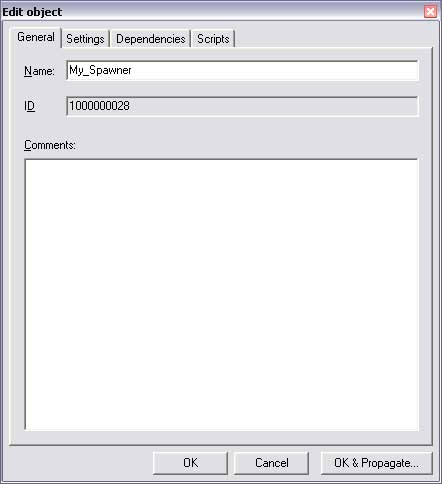
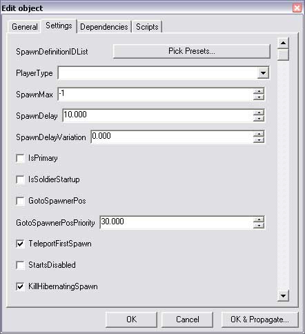
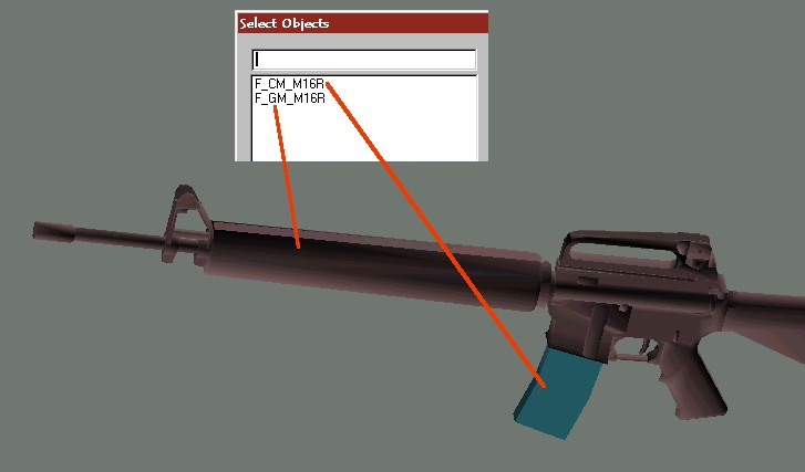
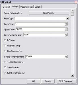
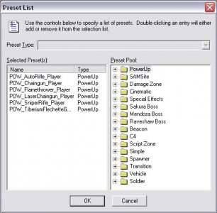
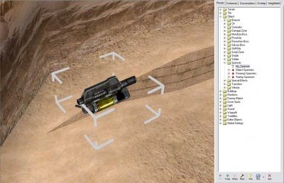
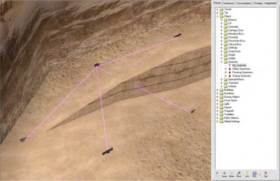
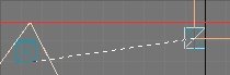
Author: General Havoc Skill level: 1 Getting Started This tutorial will guide you through making powerup spawners and adding spawn points to spawners so they can spawn at multiple places across the map as Westwood ones do. After you have read this tutorial you should be able to add spawners and spawn points on your own maps. 1) Setting Up The Spawners First thing is to load up your terrain into the Level Editor. After you have loaded it up you need to browse to Objects > Spawner on the preset tree. Next click "add temp" which should bring up a screen like below. Fill in the "Name" box with a name for your spawner then click the "Settings" tab, which should bring up something similar to below. You will see a lot of settings now, you can leave them as they are or change them. The main things you would want to change are the "SpawnDelay" which is the length of time in between spawns and the "SpawnDelayVariation" which is the added variation that is added to the time. For example if the "SpawnDelay" was set to 10 seconds and the "SpawnDelayVariation" was set to 15 seconds then the maximum time between spawns is 25 and the minimum is 10. It is selected randomly each spawn unless the value of "SpawnDelayVariation" is 0. After you have played around with the settings click the "Pick Presets..." button. It should bring up a window like below. This window is where you pick what the spawn actually spawns. You can see I have already added a few weapons, you can find them in the panel on the right side under PowerUp > Soldier Powerups > Weapon Powerups add as many as you wish, to add an item, double click it on the right panel, to remove an item, double click it on the left panel. It is a good idea to add many different weapons as when you add spawn points later you may want variation as these don`t act like individual spawners. The more times the same item appears in the list on the left, the more chance it has of spawning. After you have finished click on "ok" then "ok" again on the settings window. You should be returned to the map view with your new temp preset in the preset list. Click on your newly made spawner and click the "make" button to make it on your map. To align it to the ground, press "Ctrl + D" and then drag it around to get it into position on the terrain. You can see my spawner that i have just made on the map below. After your happy with it`s position press "Ctrl + P" to add a new spawn point. It should be linked by a pink line. Drag this copy around until your happy with it`s position. Repeat this process until you have as many as you want. Here is my may below. Don`t worry about the weapon that you see when placing them as it is just a random one selected from the list you made, in game it will be randomly selected. The thing you just did was add a "point" which is a place for the spawner you made to spawn at. It will behave like the Westwood spawners in game meaning that only one weapon will spawn at one of those points at any one time. This is a good way of reducing the amount of spawners on a map and prevent players camping the spawner for a specific weapon as the weapons that spawn change and also the places. 2) Testing Congratulations, you have managed to make a new spawner and spawn points. You can test this in game and see how it works. If it doesn`t work as you expected then read the tutorial again and check you did everything correctly. 3) Hints & Tips Here are some hints and tips that may help you when making the spawners and spawn points: Don`t add too many spawn points especially in harder to reach areas as there could be an object spawned at that location for a long time if no one can reach it easily. This will prevent any more objects spawning at other points until the one was collected. Play around with the spawn times to find out what works best. A lower time may be more appropriate. Spawners and spawn points don`t just spawn weapons, you can spawn many more things including vehicles, bots and crates, experiment with different things. Remember to add multiple objects to spawners if you want to have the spawner spawning different objects. 4) Credits This tutorial was written by General Havoc (Robert Hunt) Thank Westwood Studios for the excellent series of C&C Games. Let Westwood Live on!
-
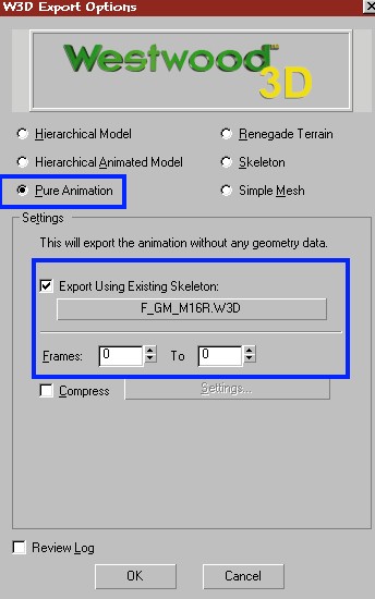
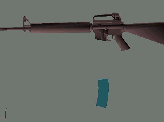
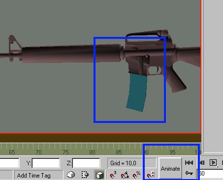
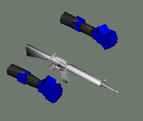
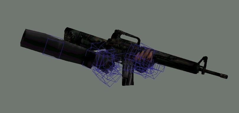
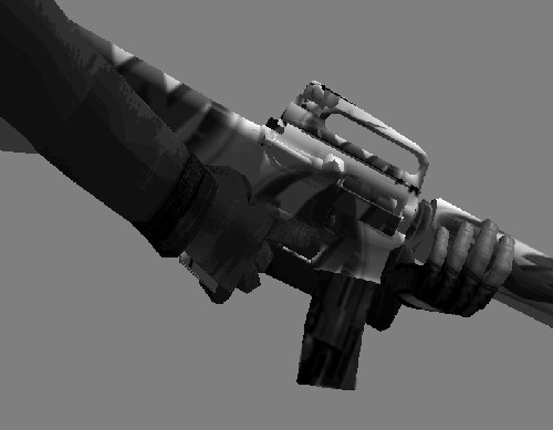
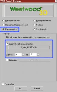
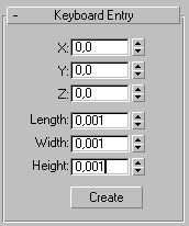
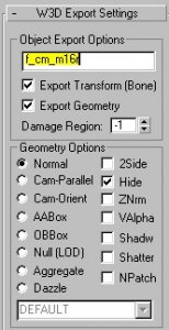
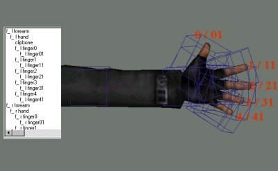
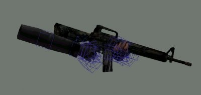
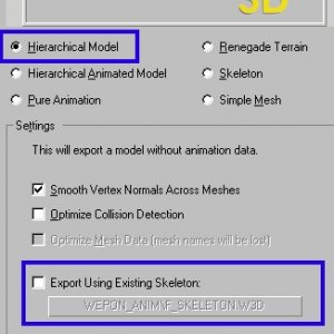
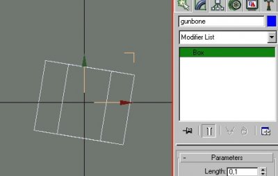
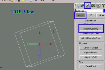
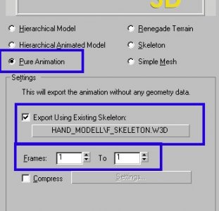
Author: Läubi Skill level: 6 !!! Important notice !!! 1. To follow these Tutorial you must have these files and the 1st Person view of your wepon. Put all these files into a folder (e.g. mywep) You must also have created your weapon for use in Renegade see the Weapontutorial ----------------PART I - prepare your weapon 2. Open you 1st Person Wepon in RenX, you must have two parts, the gun, and the clip. Choose a name (max 4 chars) I have coosen m16r, and name your gun f_gm_xxxx (xxxx = your name) and the clip f_cm_xxxx Now group thr clip and the gun, goto Hirachy -> Affect Pivot Only -> Center to object Deaktivate now the Affect Pivot Only and move the gun into the center of GMAX Now save the file and export it as f_gm_xxxx.w3d (Hierachial Model) into the folder where all the other files are. 3. Now export your file as f_ga_xxxx_idle.w3d, select Pure Animation, Frame 0 to 0, use Existing Skeleton (select here your exported f_gm_xxxx.w3d file) Do the same again, but name the file f_ga_xxxx_fire.w3d ( Before that you can make an animation, e.g. if there is a rotating gun, like the chaingun, but normaly there is no aniamtion needed at this time, the fire anim will be made later. The aniamtion here is only needed, if there is something moving at the gun while firering) 4. Ungroup now the wepon. Now it is time for the relaodaniamtion. For that you should know, how long it takes for your gun, to reload (this will be set up in Commandoeditor). Now calculate the needed frames. Needed frames = ( 30 * reloadtime ) If you have the needed frames divide them by 2. Move to this frameposition and a click Animate . Move now the clip down, so that it is unloaded. Now move to the needed frame and move the clip back, so that the clip is back at the old pose. Now click again at Animate. Now export your file as f_ga_xxxx_relod.w3d, select Pure Animation, Frame 0 to (the end frame), use Existing Skeleton (select here your exported f_gm_xxxx.w3d file) Your reloadaniamtion is now done. Select the gun and the clip and make a groop of them. Save your work. Of course it is possible to make any other aniamtions for the reload, but this is an easy and effective way. Now make a new file, and just create an 0,001 x 0,001 x 0,001 Box ->name it f_cm_xxxx and select hide at the W3D Options now export the file as f_cm_xxxx.w3d as Hirachial Model ----------------PART II - do the handposition and the animations 5. Open now the gun_hands.gmax file, and save it under a new name ( e.g. m16r_hand.gmax ) now goto file->merge and merge your 1st Person weapon into, save your work. Rotate your grouped gun now, so that the gun is on the right position between the both hands. (use only the rotation tool, to prevent missposition) The blue boxes are the bones, that are affecting the handposition. Press `H` to diplay all Objects in the scene, activate [x] Display Subtree, you see now the linking of the bones. I recommend to use this dialog later to to select the bone you want to aniamte. YOU MUST ANIAMTE THE BONES INSTEAD OF ANY PART OF THE HAND OR WEPON OR IT WILL NOT WORK. The bones are what they named, f_l_forearm = left forearm, f_l_hand = left hand the fingers have a simple system: With the (n = 0 - 4) f_l_finger n - bone you can move the finger at the hand, with the f_l_finger n1 - bone you can bend the finger. 6. We will now do the standard hand position, I recommend that you spend a bit of work for this, because this basepose will later be used too for the reloadaniamtion etc. Of course you can make for every state (enter/exit, fire, reload, idle) a seperate handposition, if that is needed. Now click the animate button, and move to frame 1. It`s important that you move to frame 1 and has enabled the Animate or you`ll later get in trouble with exporting!!!! Then select the bone you want to change, and move the fingers, hand and forearm into the position you want. I recommend that you only rotate the fingerbones, or the may look too long or deformed. If you want to test the handposition export your Model as Hierachial Model, and deaktivate [ -] Export using existing skeleton 7. When you are ready with the handposition you must select the bone: `gunbone` and move it exactly to the pivot: Now go to the hirachy tab, select pivot -> Affect Pivot only, and rotate the pivot of the bone (Use Top-view) so that the green arrow stands in an 90° angel to the worlds green arrow (y - Achse) and the red arrow stands in a 90° angel to the green and red arrow. Now the most work is done deaktivate the animate button, save the file. Now hide your wepon, and export it as f_ha_xxxx_idle.w3d select Pure Animation, Frame 1 to 1, use Existing Skeleton f_skeleton.w3d 8. Now it is time for the fireanimation. Save your file with a new filename e.g. mywepon_fireanim.gmax I can`t say directly what to do from now on, because it depends on your wepon, and you can`t "see" a animation on pictures. A good idea is to animate the forearm bones a bit. But only animate the handbones, not the weapon! Then save, hide the wepon and export the file with the same settings as before, but at the frames use 1 to (lastframe you used) name the file f_ha_xxxx_fire.w3d 9. Then open the gmax file with your standard handposition and save it again with a new name e.g mywepon_exit.gmax Make now an aniamtion for the exit of your wepon, e.g. rotate the forearm bones, so that it looks like the wepon gets behind you. Export the files with the already known settings as f_ha_xxxx_exit.w3d Repeat these with an enter animation and export as f_ha_xxxx_enter.w3d 10. Now comes the final step, the relaod animation. For that load your standard handposition file again, save it e.g. as mywepon_relaod.gmax Ungroup your wepon, so that the clip when you aniamte the handposition moves too. Goto frame 1 and press animate and change the base position if that is neede, so that the hand holds the clip and the move to the frame when the clip is `unloaded` and correct the handposition. Then move to the frame, when the clip is attaced to the wepon and correct the handposition again. Export it with the same settings as before and name it f_ha_xxxx_relod.w3d ----------------PART III - insert your files and enjoy your work 11. Copy now all .w3d you have exported into your Mod folder, setup your wepon in Commandoeditor and select as 1st Personview the file f_gm_xxxx.w3d 12. Export your Modpacket and ENJOY! F.A.Q. Question: My wepon is a bit to high/low or has not the postion it should have Answer: Rotate or move the gunbone bone Question: The handposition and animations works fine, but the clip don`t move while reload. Answer: Check if you have exported the f_ga_xxxx_relod.w3d right (check start/endframe, and the naming) Question: How do I add an emitter to the first person view mode? Answer: You need to add and link the emitter to the gun model (f_gm_name) and then hide/unhide it using visibility tracks when exporting the f_ga_xxxx_ animations. E.g. for an emitter to only show up during reload, you need to hide it in enter/exit/idle/fire and make it visible in the relod animation.


-
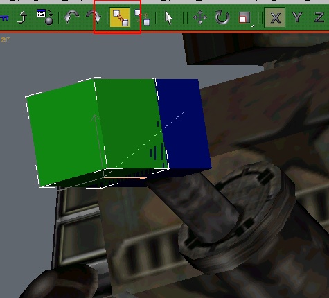
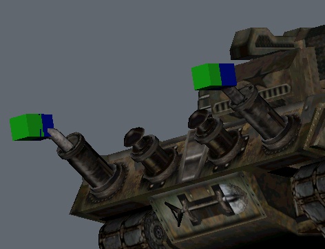
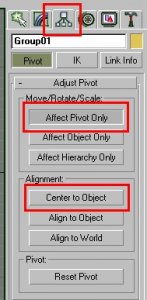
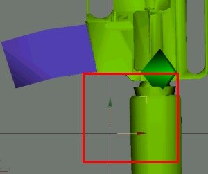
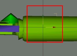
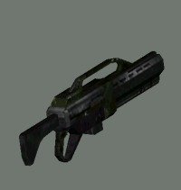
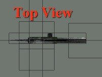
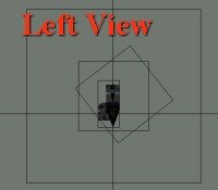
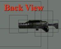
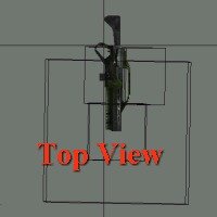
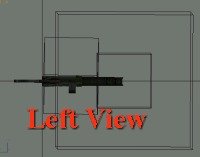
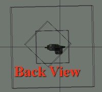
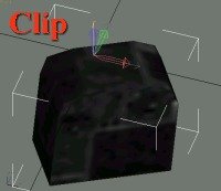
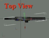
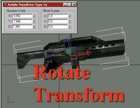
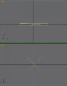
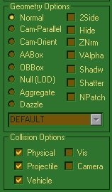
Author: Läubi Skill level: 5 Posted on October 15, 2002, by Abjab at the Westwood Forums Edited, reformated and images added by Läubi on June 4, 2003 [edit: I have reformated the tutorial as well as adding some comments with knowledge that was found out later and things I have found out myself. Additives are marked with a red `edit` plus a number -Läubi ] Ok I know allot of you people have been trying to figure out how to create your weapons so they are correctly positioned and oriented depending on if its viewed in 1st or 3rd person or if its on the character`s back. Well I`ll try to make it easy to understand. First you need 3 individual models for the weapon. it`s always a good idea to use same name convention WW uses for their models, I`ll use the auto-rifle weapon for the example. [edit1: If you do this you can use the reloadanimation and handposition of the WS weapon, if you do not find a weapon that fits your needed handpostion/reload animation you can create your own one for this see the Handposition Tutorial] Weapon models for 3rd person view are named like this: w_rifl.w3d (where rifl is your weapon name) Weapon models for when the gun is on the character`s back are named like this: w_rifl_b.w3d Weapon models for 1st person view are named like this: f_gm_rifl.w3d 3rd person weapon models: All characters have a "gun bone" that tells renegade which hand does hold the gun. the weapon`s pivot point is positioned at this "gun bone" position. In other words, once you have created your weapon mesh, move its pivot where you want the hand to be. You fix the style that the character should hold the gun in Level Editor i.e.: Shoulder: uses both hands (second hand position is set automatically by Renegade) Pistol: uses one hand etc... [edit2: This is only autosetup for 3rd Person view! For 1st Person view see edit1] Now the weapon and its pivot needs to be correctly oriented in RenX: Weapon Orientation: Viewing from top, the weapon should be pointing to the right, and the top side of the weapon is facing you. File: w_rifl.gmax/w3d Pivots Axes: X is pointing to the front of the gun (right in top view) Y is pointing to the top side of the gun (pointing at you in top view) Z is pointing to the right side of the gun (down in top view) Weapons Bones: MuzzleA0, A1: position at which bullets are fired, muzzle bones pivots axes are oriented the same way the weapon`s pivot is. eject: position at which shells exits, its pivot`s Z axis is pointing to the back of the gun and its pivot`s X or Y determines which way the shell exits (I think X does) [edit3: As far as I know the eject bone is obsolent for 3rd person view because Renegade do not show the outcoming clip in 3rd Person view] Origin: use world axes coordinate, positioned a little back of the weapon`s pivot (approximately at elbow`s position) [edit4: from my experience this affects the position of the elbow if you use an twohanded mode like shoulder in Leveledit as mentionted before.] If you use a muzzle flash aggregate, link it to the muzzle just like for vehicles. 1st person weapon models: For 1st person view, you can use the same model, or create a simplified version of it with details only in the viewable parts of the gun. Also, for 1st person view, you have to create a magazine mesh for the reload anim. [edit5: Better use a simpler version of the weapon for 3rd Person view than for 1st Peron view!] Like for 3rd person view, the weapon`s pivot position determines where the hand should hold the gun. Weapon Orientation: Orientation of the weapon for first person view is different then the 3rd person. Viewing from top, the weapon should be pointing down, its right side facing you. File: f_gm_rifl.gmax/w3d Weapon Pivot axes: X is pointing to the top side of the gun (right in top view) Y is pointing to the back side of the gun (up in top view) Z is pointing to the right side of the gun (pointing at you in top view) Magazine Pivot axes and position: X is pointing to the right side of the gun (pointing at you in top view) Y is pointing to the back side of the gun (up in top view) Z is pointing to the top side of the gun (right in top view) The pivot of the magazine is positioned at the top of the magazine mesh (pivot`s Z max), back most of the magazine (pivot`s Y max) and left most of the weapon side (pivot`s X axis). The magazine mesh itself is positioned wherever you want it to be on the gun. Name the magazine: f_cm_rifl (where rifl matches your weapon`s name) Weapons Bones: MuzzleA0, A1: for 1st person view, muzzle bone uses a different pivot orientation, X points direction of bullets (down in top view) Y is pointing to the right side of the gun (pointing at you in top view) Z is pointing to the top side of the gun (right in top view) eject: eject bone`s pivot orientation is also different from 3rd person view, X should be pointing direction of shells to exit (right, up 45 degree) Y is pointing to the back side of the weapon (up in top view) Z is pointing right, down (45 degree) Origin: Origin might be determining how far the gun is from the camera, in the auto-rifle w3d, it is centred to the weapon`s pivot position, aligned with world coordinates. [edit6: in fact this is the bone that gets attached to the gunbone of the character. How far the weapon is away from your Character is setup in Leveledit.] Back weapon models: This is the model used when on the back of the character, there is no bones for this model. Only the mesh itself and its origin. Weapon orientation: Same orientation of the 3rd person model. Viewing from top, the weapon should be pointing to the right, and the top side of the weapon is facing you. File: w_rifl_b.gmax/w3d Weapon`s pivot orientation: Since it is on the character`s back and that the weapon is not straight on the back, the pivot axes determines the angle of the weapon on the character`s back. Since this would be hard to explain, here`s the XYZ rotation in absolute world coordinates for the auto-rifle. To set your weapon`s pivot rotation simply click on the "affect pivot only" in the hierarchy tab, then right click on the rotate tool and type this in absolute world X,Y,Z: X: -0.9516 Y: -7.6463 Z: 7.3055 Weapon`s pivot is centred with the weapon Origin is positioned at the same point where the hand should hold the gun in 3rd person view. (weapon`s pivot point of 3rd view model) Origin using world axes coordinate as always. [edit7: I dunno what Ajab means with that, but you just need to center the orgin to the weapon.] Finish: Ok that`s it for the RenX part, now all the rest is set in Level Edit, try messing around with settings until you get the results you wish. [edit8: You can now start with doing your own handposition and reloadanimation if you want one. For informations see edit1] Hope that helped, Abjab [edit9: I hope that too, and I hope my notes help you to better understand this Tutorial. Have fun with the Tutorial and modding for Renegade] You can download the files I used to create the screenshots here. This is just the standard rifle imported into Gmax, I have corrected just the textures a bit and set the bones so they are not visible after export.
-
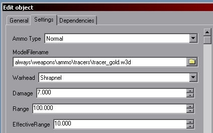
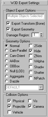
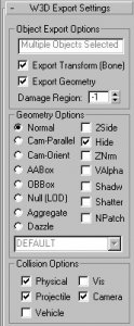
Author: Oblivion165 Skill level: 1 Projectiles Projectiles are simple a small low-poly mesh. For instance, this is what the Renegade MiniGun Shoots: To make a projectile for a gun, simple model a bullet or lazer, center it in gmax, and export it as a "Hierarchical model" with these settings: and add it to level edit as ammo: Set the weapon that you want to use this for, to use that new ammo type. After seeing it ingame, shink/enlarge it to the right size. You should be good to go. Enjoy Melee Weapons To make melee weapons, such as knifes or swords, etc. Simply make a invisible projectile (1x1x1 Square will do), Center it in gmax, apply these settings: Export it as a "Hierarchical model" and add it in level edit as ammo, in its settings make its range short, 1 or so, and make sure you change the effective range to the smaller number as well. Thats it, enjoy. Written by Oblivion165
-
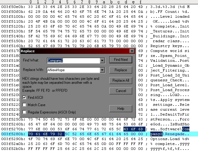
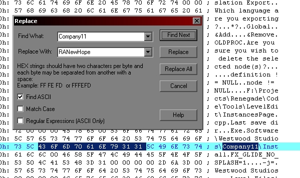
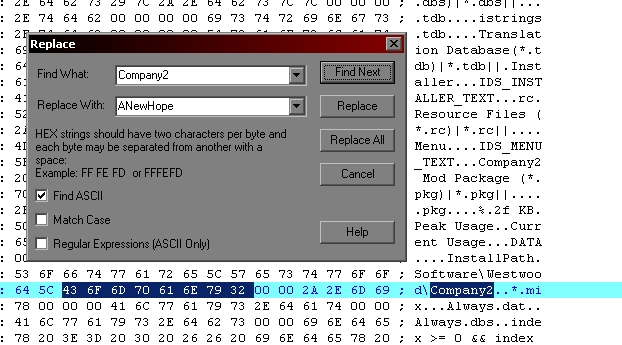
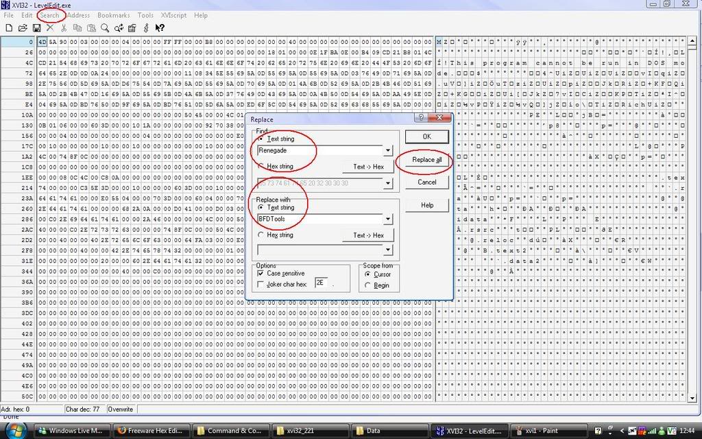
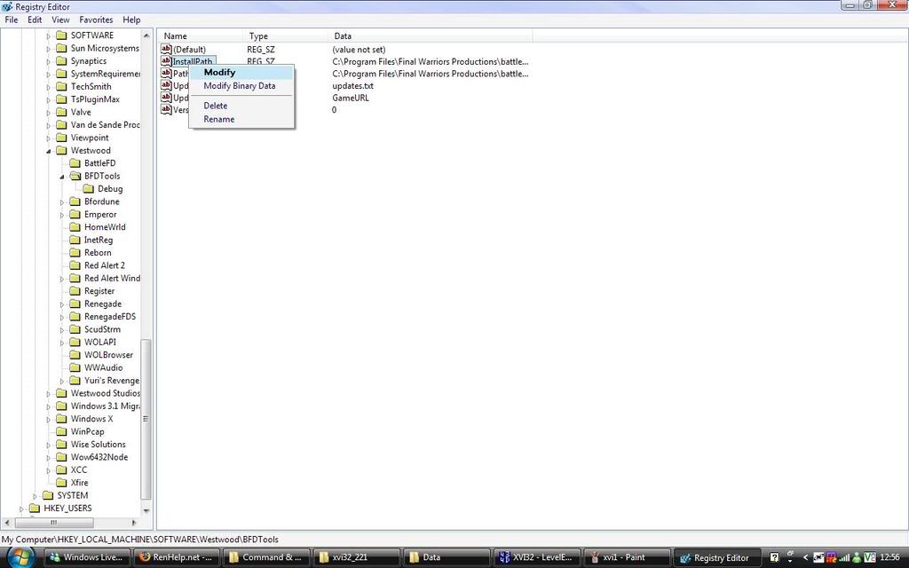
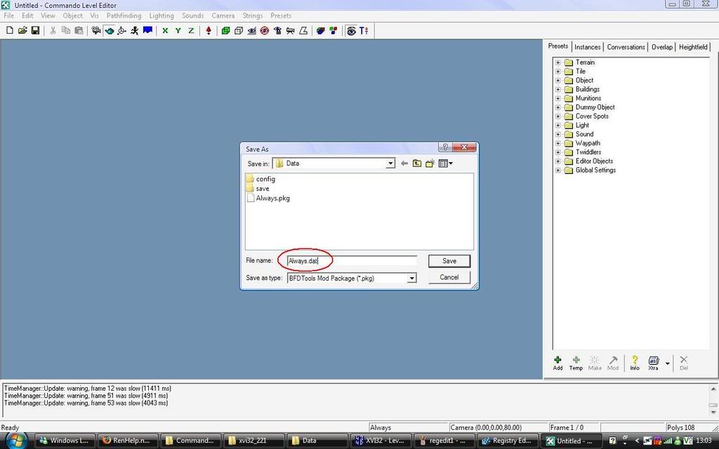
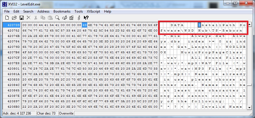
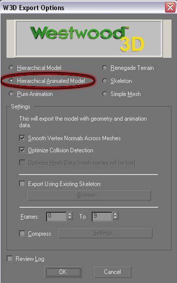
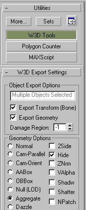
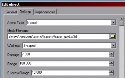
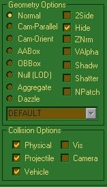
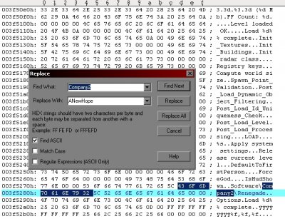
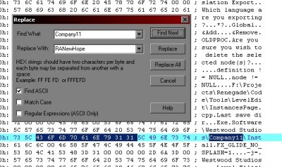
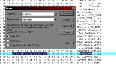
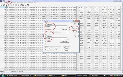
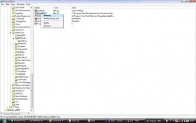
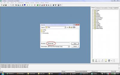
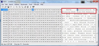
Author: moonsense715, Oblivion165, cnc95fan Skill level: 3 This tutorial will show you how you can create your own custom, standalone W3D game and a Level Editor tied to it. 1. The game Before you can make your game and its own editor, I highly recommend basing it off of something. So firstly, make sure you have a W3D game downloaded (e.g. using the launcher). Make a copy of the game's entire folder, where game.exe is sitting. Now you have a duplicate of your reference game. Find the paths.ini file in your copied game's Data folder. If there is none, either extract it from always.dat (using Xcc Mixer or RenegadeEx), or create a new file, with the following content: [paths] RegBase=W3D Hub RegClient=games\tsr-release RegFDS=games\tsr-release-server FileBase=W3D Hub FileClient=games\tsr-release FileFDS=games\tsr-release-server UseRenFolder=false RegBase/FileBase is the folder's name in your Documents folder (e.g. the developer or company name), and RegClient/FileClient is the subfolder with your game's name.Change all the folder names to match your game. Then save it as paths.ini. If you go ingame and hit Print Screen to create a screenshot, it should now be saved under \Your documents\Your specified subfolder\Screenshots folder. Your standalone game is done, but of course you will want to fill it with your own content. And for that you will need your custom Level Editor. 2. The editor If you do not have it yet, download the editor that is designed for your reference game from here. Otherwise, copy your LevelEdit folder. At the moment, your copied editor is tied to the reference game. You need to hex edit your LE to have its registry key point to your new game. Download the HEX editor XVI32 and open your LevelEdit.exe with it. Now search for InstallPath in non case-sensitive mode. The Reborn Editor for example, has it's reg path under W3D Hub\TS-Reborn. You need to REPLACE (CTRL + R or Search -> Replace) TS-Reborn (or whatever is there) with your own game tools' name that you choose. For example you can use MyGame-LE. Make sure this name is max 11 characters long. Don't forget to replace W3D Hub or whatever is before \your-game-name, with your own studio name. Save the edited LevelEdit.exe, your job here is complete. Now just drag and drop LevelEdit.exe onto leveledit_path.exe (don't have it? Get it from here), choose your game's folder where game.exe is sitting and boom! You have your Editor set up! For older W3D games where paths.ini does not exist or work at all, the tutorial for how to make your custom game and editor is below.
-
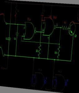
Vehicle/Building/Infantry - Energy/Projectile creation - W3D
moonsense715 replied to Shnappz's topic in Community Creations
If you ask all the questions before the tutorials go online there will be no point putting them up -
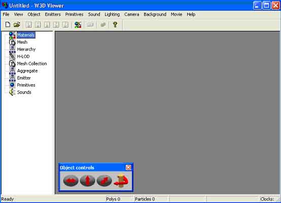
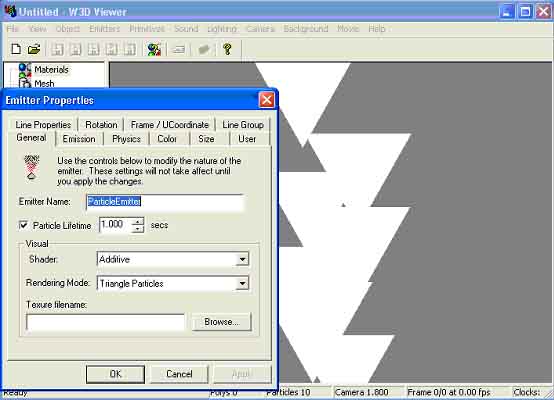
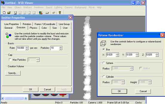
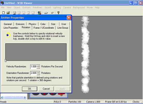
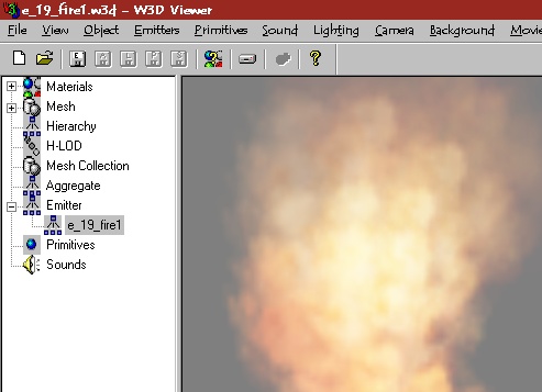
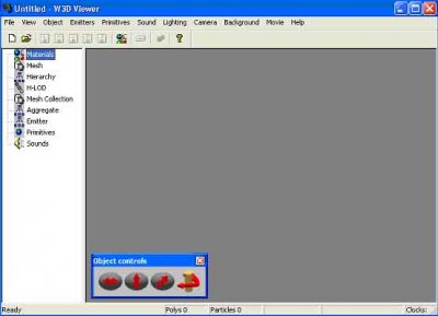
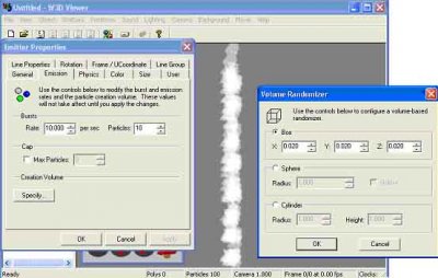
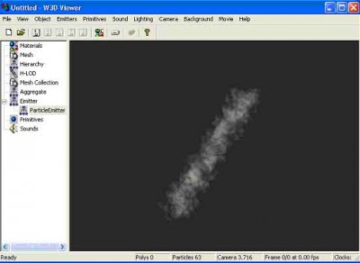
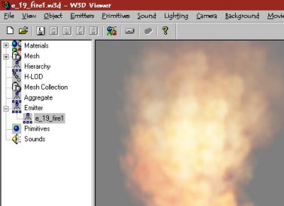
Author: Genocide Skill level: 3 Emitters serve purposes such as the smoke trail for the Rocket Launcher and Tiberium Dust. Creating a successful emitter is easier than you would of think, all you need is the Renegade Mod Tools which if you dont have you can get here: Renegade Public Tools After you have got that, browse for the mod folder, which generally is: C:\Program Files\RenegadePublicTools\W3dView, after that you will see W3dview.exe, open that and you should see the following: After the program is open, select the Emitters tab located at the top menu then choose, Create Emitter, when that happens the following window will open where you will edit all your settings: Here you shall name you emitter anything you wish, I suggest if you are making a smoke Emitter you leave the Particle Lifetime to 1.000 Secs, for future reference, the longer the Lifetime the longer the Particle Trail. I have changed the Rendering Mode To: Quad Particles Now we are going to add a texture to the emitter, you can do so by going to browse and search for a .tga file extension file. (If you have a texture and want to convert it to a .tga file then download advanced paint programs such as Jasc Paintshop Pro, and Adobe Photoshop) After Selecting, the best shader for a light Smokey texture would be Screen, after selecting that the texture we need to move to the Emission Tab where we will change the Density of the Emitter this is what I have done by editing the Particles, Rate And Creation Volume : Now, Notice the more dense the emitter has got, now time to move to the Rotation tab, I have skipped a few tabs because they will not necessarily be needed when creating a smoke Emitter, here I have edited rotation to make the emitter look more realistic: Now we are finished with the Very Basics of creating an emitter , I suggest playing around with this program to find out just what amazing emitters you can make, even ones that have sound attached to them! , I hope I have entered you well into the world of emitter creation, after playing around some more here is my finalised smoke emitter : Thanks for reading my tutorial and I hope that you become a great emitter creator, Genocide.


-
Level Edit: Physics Model tab of your vehicle. Decrease mass / increase max engine torque to make it go faster. Adjust all the other values accordingly. Fastest way to test what each value does is to host yourself a 1 player game and hit F8, then type in: edit_vehicle. It will let you modify most of the values (but not all) on the fly.
-
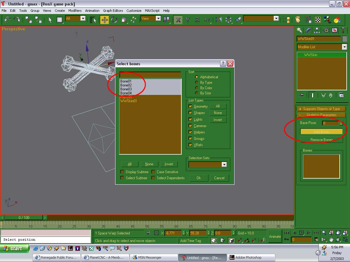
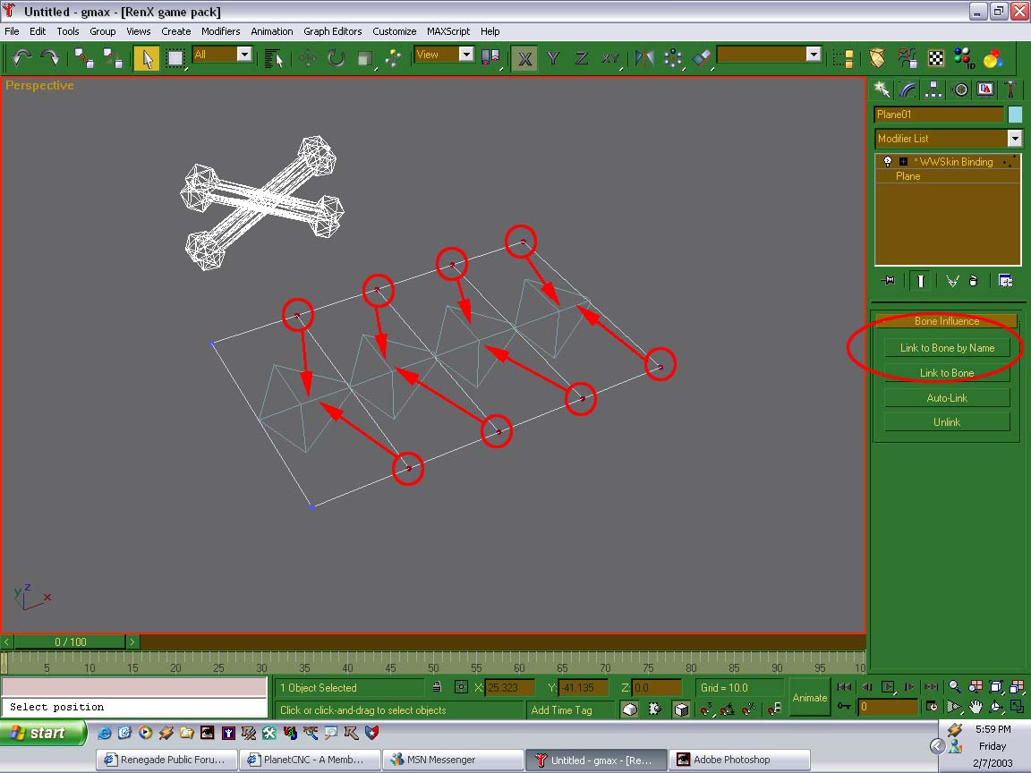
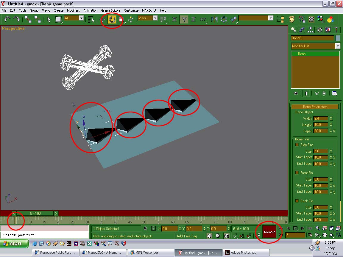
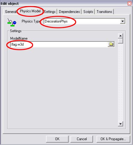
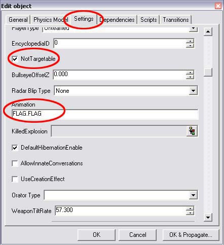
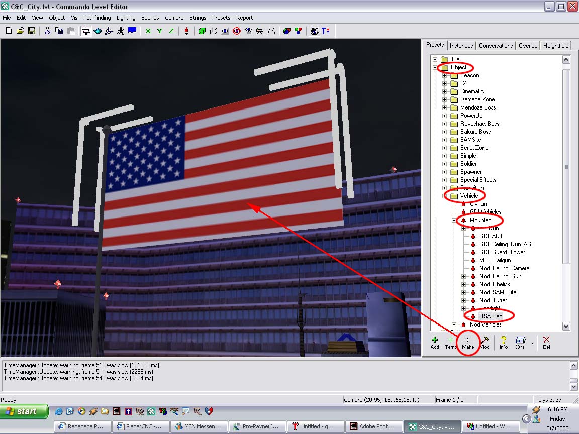
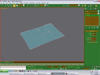
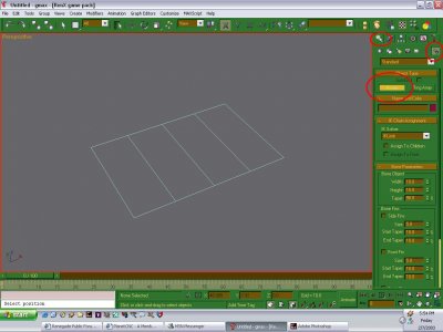
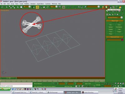
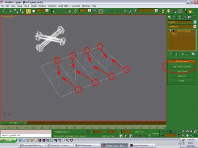
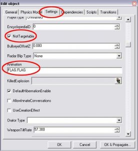
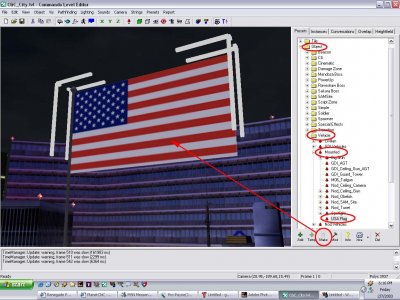
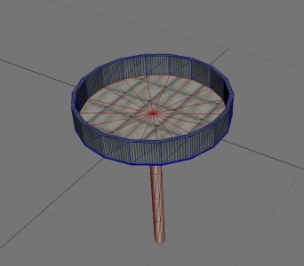
Author: General Havoc, Havoc 89 Skill level: 3 In this tutorial you will learn the basics on how to make rippling effect. This tutorial can be used to make rippling flags, water, etc... Step 1 Create a plane with at least 4 or more "Width Segs". Step 2 Press F3 (Wire Frame Mode). Go to the create tab and select "systems" (looks like two gears) then click on "Bones". Step 3 Select the "Bone" button and click once on each Width Seg. Step 4 Click "Create Renegade Skin" on the top right and make one. Step 5 Click on the Renegade Skin. Click on "Add Bones" in modifier tab and add the bones that you have made. Step 6 Click on "Bind to Spacewarp" button on the top corner beside "Create Renegade Skin" button. Press and hold the plane after clicking on bind to Spacewarp button, move you mouse over to the renegade skin and release the button. You should see the renegade skin go darker for 1 second and then go back to being white. Step 7 Click on the plane and select 2 vertices and link them to their bones. The circle bones represents which 2 vertices are selected. The arrow represents which vertices are linked to which bone. You should hear a sound when you have successfully linked them. Step 8 Press the "Animate" button (bottom of the screen). Select the rotate button on the top. Click on one of the bones and then start making a rippling effect animation. Note, you should see the plane moving as well. Step 9 After you have done with animation select all the bones and go to W3D options and uncheck "Export Geometry". This hides the bones so they don`t appear in game. Then export as a an hierarchical Animated model Step 10 Press "Add" in level edit under Objects > Vehicles > Mounted. Name it and then under :Physics Model" tab. Change Physics Type to DecorationPhys. Then use your object that you exported. Step 11 You will need the right settings. Under the "Settings" tab change health to -1 and Health Max to -1. Then Scroll down until you see something called "NonTargetable", check it off and right underneath it, you will see an animation bar which says "Animation" Enter your Flags Animation name. To find out your animation name run W3D Viewer and load your object, then click on the "+" sigh on Hierarchy. You should then see your object name with a "+" sigh behind it. Click the "+" sigh, then you should see your objects animation name. Example: "FLAG.FLAG" this is what my animation name is for my flag. Step 12 Click the "Make" Button in level edit and place your flag anywhere you want. Finished Enjoy your first rippling flag! BTW: You can also use this for other things, not just flags. You can also do this with water. Congratulations you have passed Basic Rippling Effects Tutorial. Credits This tutorial was originally written by Havoc 89. The tutorial was converted to HTML format and edited by General Havoc. I`d like to thank Havoc 89 for originally writing this tutorial and I hope it is now more useful to people in a better format. Also many thanks to the many people who help on the Westwood Mod Forums. Finally of course Westwood Studios for the excellent series of C&C Games. Let Westwood Live on!


-
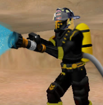
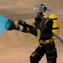
Lol, the very capable disc thrower is playing with his explosive disc/grenade in the background.
-
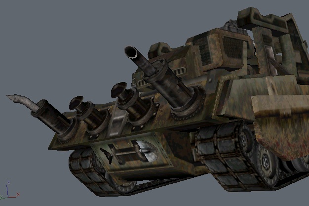
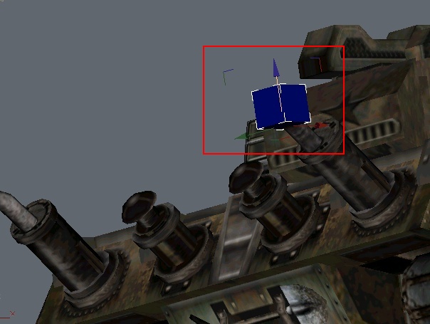
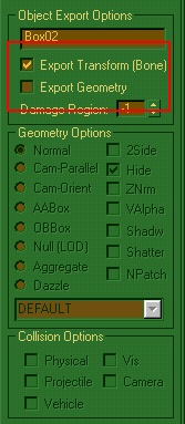
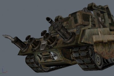
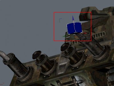
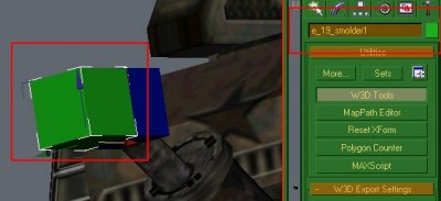
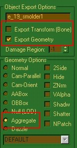
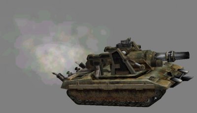
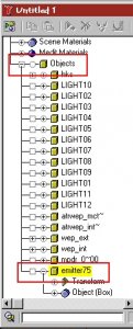
Author: Läubi Skill level: 2 1. First, you need some smoke for the exhaust, i`ll use: e_19_smolder1.w3d 2. Now you should open your Vehicle in RenX, I`ll use a Westwood made one for this tutorial: 3. I`ll just make the exhaust fumes for one of the exhausts but it will work the same for the second one. create a box 1x1x1 at the place where the exhaust later should apear Deactivate the [ ] Export Geometry for the box 4. Clone this box, and name it like the emitter you want to attatch. Deactivate the [x]Export Transform on this cloned box and Activate the (*)Aggregate on the W3D Tools 5. Next step is link the emitterbox to the exhausbox, just use the Link tool, Drag and drop from the emitterbox to the exhaustbox and you are done. 6. Repeat this for the second exhaust: 7. Now export your model, and put the model and the emitterfile into the same directory to test your work: 8. You can rotate the emitter by rotating the exhaustbox. Have Fun!


-
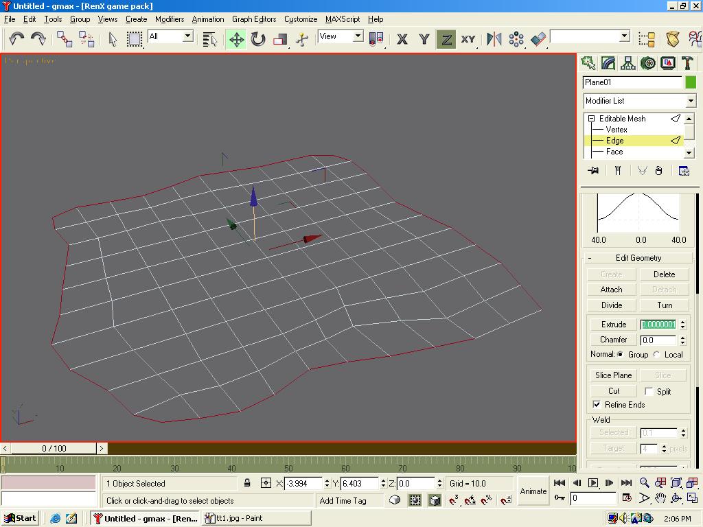
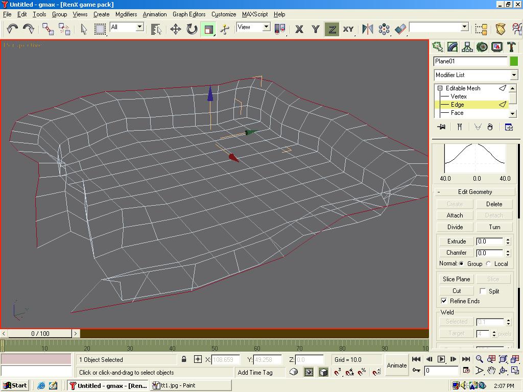
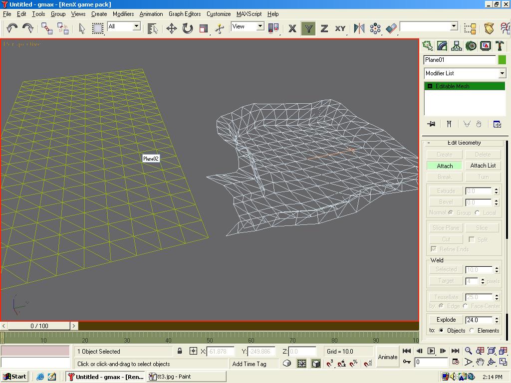
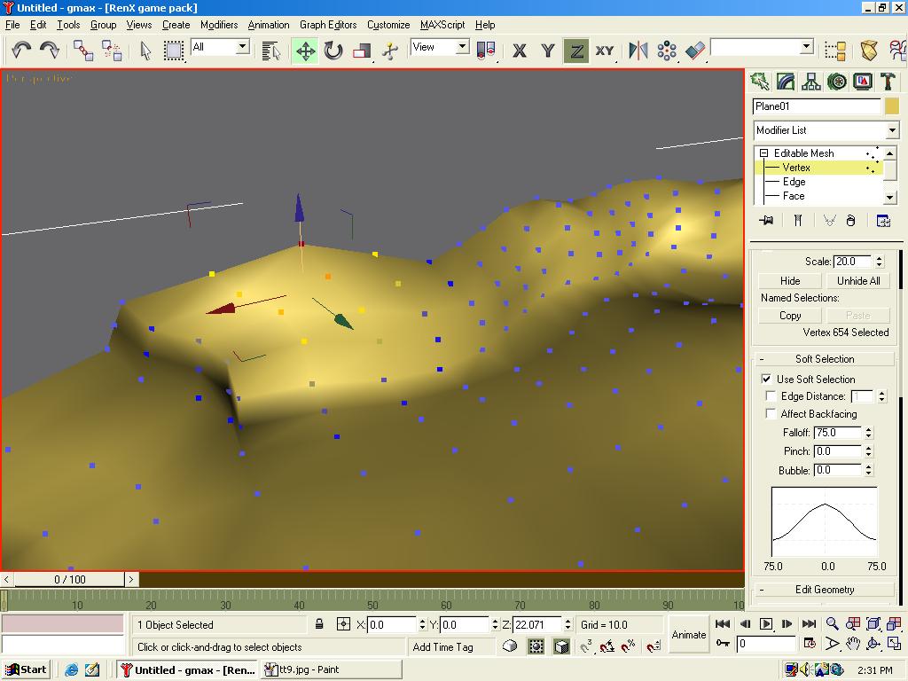
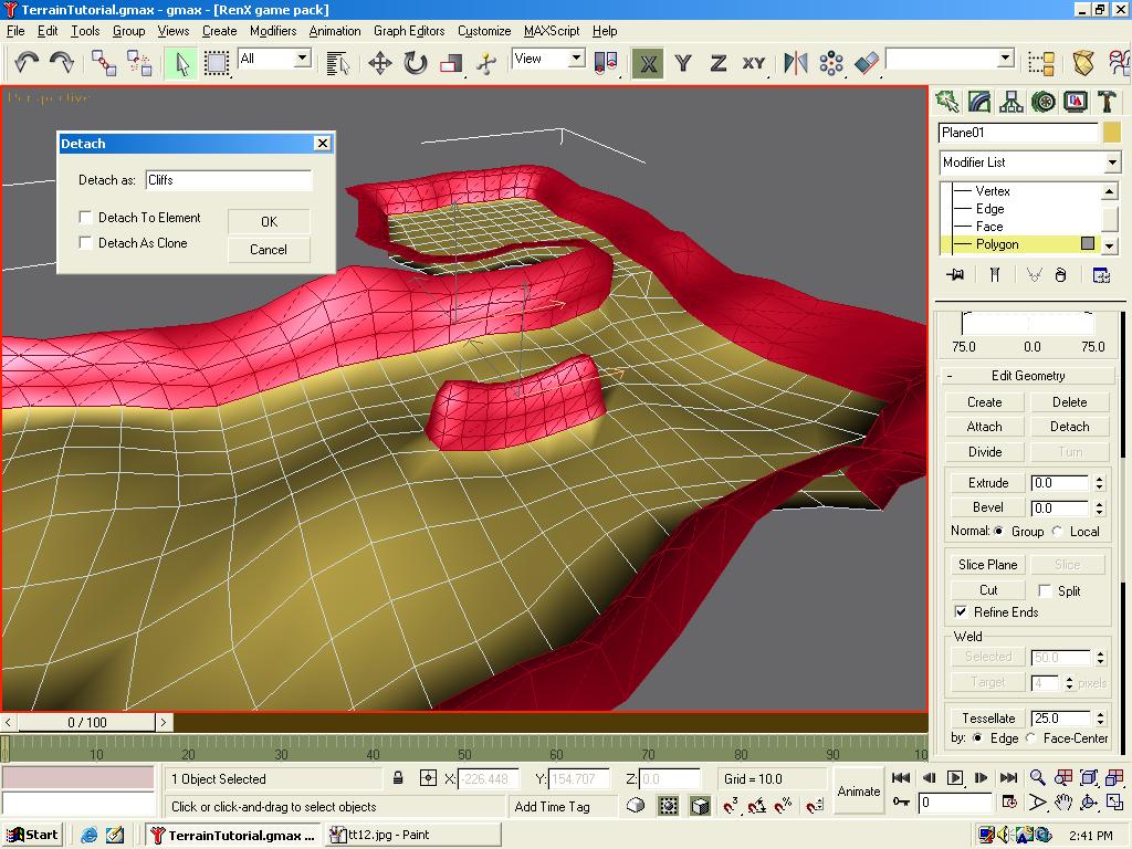
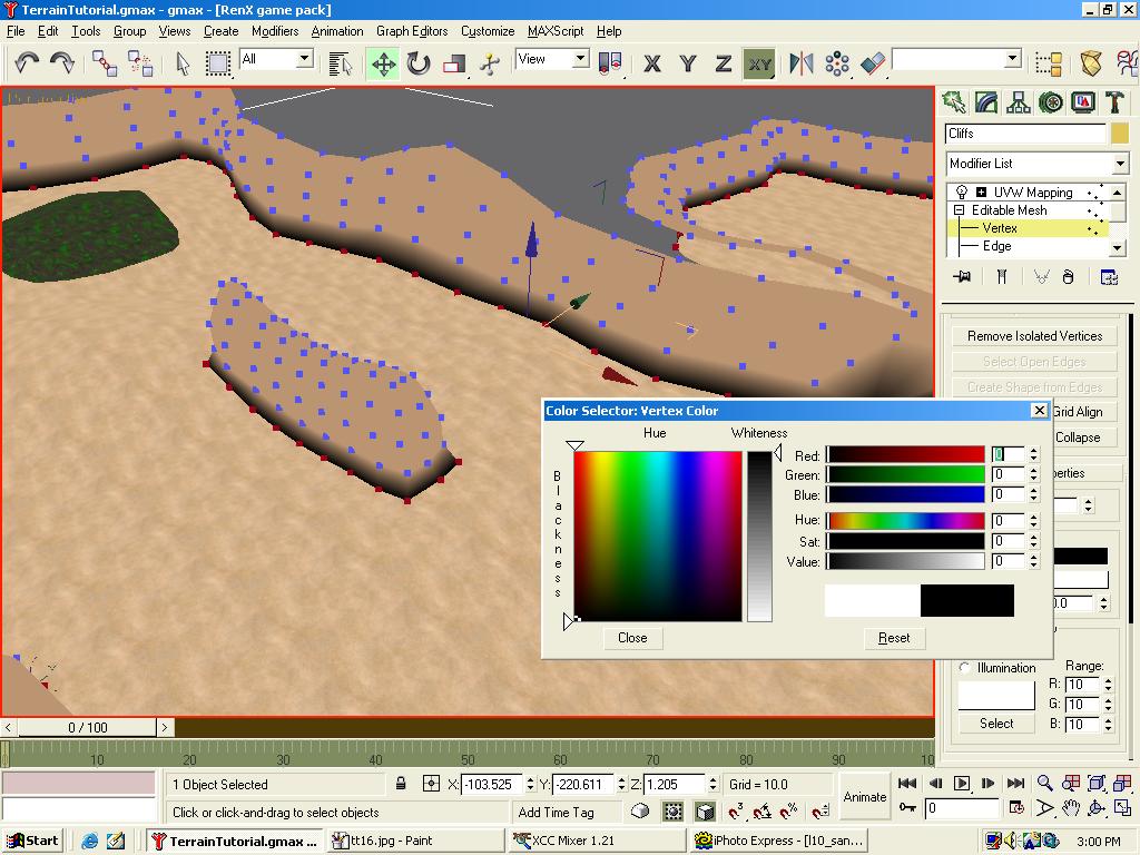
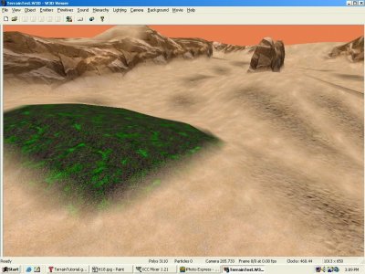
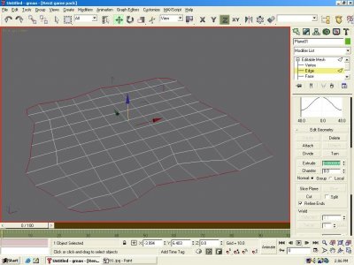
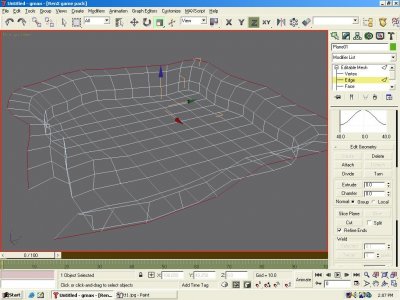
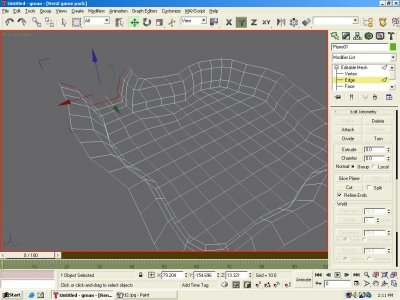
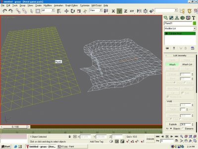
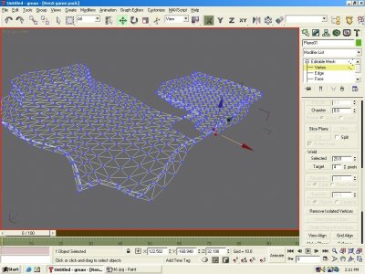
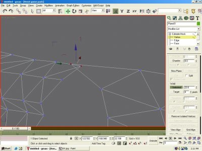
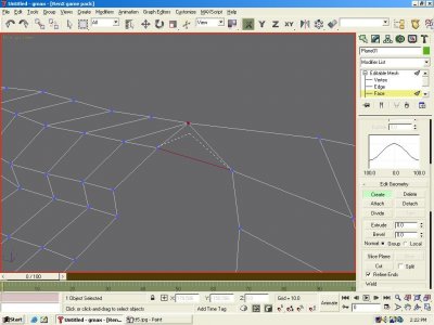
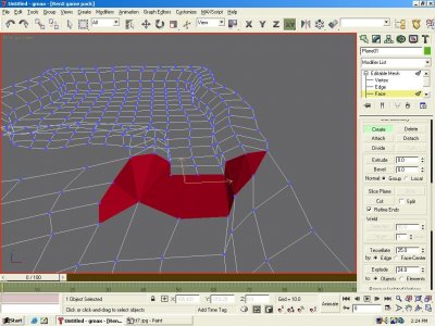
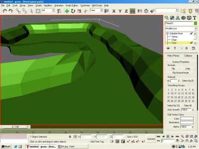
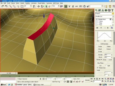
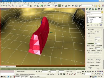
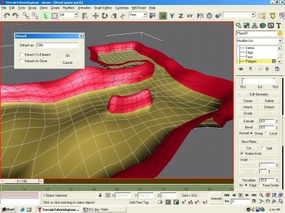
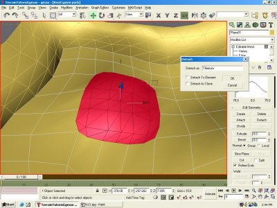
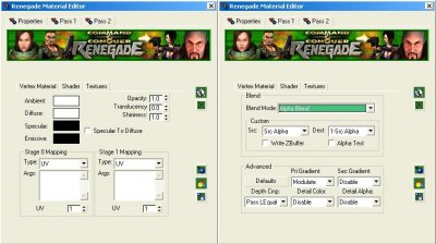
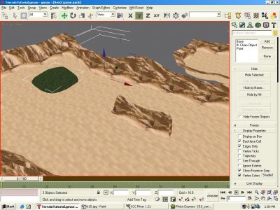
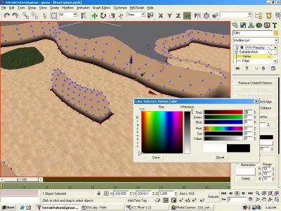
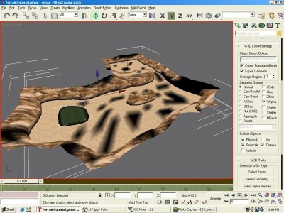
Author: SomeRhino Skill level: 2 Download the Models here Creating terrain seems like a cumbersome job is you envision aligning planes and boxes only to yield flat ground and blocky mountains, but if you know how to use Max properly, it can be done neatly and in a relatively short amount of time. Note however that this only covers the basics of creating the terrain meshes, nothing advanced. When you create a C&C mode map, you`ll need to align the buildings with the terrain. I also am assuming you know how to navigate gMax, and how to do apply basic textures. Texturing tutorials are aplenty. Start off by creating a plane. Convert it to an editable mesh (right click) and drag the edge vertices around using soft selection (found by expanding its tab under Editable Mesh. Round it out a bit to form the base ground. Select the outer edges of the mesh. Scroll down to Extrude on the sidebar and set the value to 0.00000001 or similar to keep the extrusion from going anywhere. Hit the Extrude button, and drag the edges vertically. Hit it again, and repeat. Note: a much faster and better method for extruding is to move your mouse above the Z arrow, hold shift and drag that Z arrow/axis upwards. Use the scale tool to make the edges curve outward (mouse over the Z arrow/axis when scaling outward). Do this one or two more times until the edges cannot be seen from the ground below (by the players). If you don`t have one already, create an opening by deleting some polygons (select them and hit delete on your keyboard.) Drag a few of the vertices to make an outer angle. Now select the edges on the opening and extrude some more to create an exit to the area. Now create a larger plane, which you will make into the main area of the map. Attach the meshes together using editable mesh. Shape the new plane into more terrain using soft selection on the edge vertices and extruding some more. Now it`s time to connect the two objects together with polygons. Select vertices that are relatively close to each other and in the Weld box, set the value next to Selected to however many meters from each other you estimate the vertices are distant. Hit the "Selected" button, and they should weld. If you get an error, increase the value. Hit the Face branch on the Editable Mesh tree and hit the Create button. Build face by clicking on three vertices consecutively in Counter-Clockwise order. Hitting them clockwise will build a backface. Build more faces to completely connect the objects. If you switch your view to smooth + highlights, you`ll notices that your level will be very faceted and blocky looking. Remedy this by selecting all the faces and scrolling down to the Auto Smooth button. Set the value to 180 and click it. I have changed my terrain's color to look more like a desert. This is not the texture though and is merely for my myself during the modeling process. Now, use soft selection to drag vertices smoothly on your mountains and ground to give the terrain a more realistic shape. When you move a vertex with soft selection on, gmax/max will automatically also move the surrounding vertexes by a certain amount toward the same direction. The amount is merely indicated by colors on every vertex and can be controlled by Falloff, Pinch and Bubble. Aircraftkiller taught me an easy technique for creating ridges. Select a few of your ground polygons and extrude them up a couple times scaling them down a bit each time to give the ridge a tapered look. Now, select all the polygons that make up the ridge and find the Tessellate button. Leave it as Edge and 25, and just hit the button. It will smooth out the ridge with more polygons. Again, you need to run the Auto Smooth on your terrain. Now it`s time to divide up your meshes. Select the mountain polygons. I selected mine by going to the front view and selecting the higher polygons. Clean up by holding down the Ctrl key on your keyboard and selecting/deselecting polygons my clicking on them. Hit the detach button on the sidebar, name it, and hit OK. If you want to make a tiberium field, select a few polygons, Tessellate them with a value of 0 this time. Move the vertices around to give the tiberium a boarder, which will be the blending area. Detach it as you did the mountains. Now, set up your materials with 2-passes. Pass one should be the texture you want blended onto the main texture. Don`t hit display on the texture until you have both passes set-up, or RenX will crash. Pass 2 will be the main texture. Set its Ambient and Diffuse settings to white, and its blend mode to Alpha Blend. Apply the materials and texture accordingly. You`ll want to have display set up on the second pass to all your materials. I have 3 materials: Cliffs, Sand, and Tiberium. The Cliffs and Tiberium you`ll want to have a sand texture on their first pass, so that you can blend them seamlessly into the ground. For pass 1 on sand, I have an alternate sand texture. I`ll use blending to eliminate the monotony of a single ground texture. Now, go to the display tab on the sidebar. Select all the objects and put a check by Vertex Colors. Select the vertices that you want the blended texture to appear on, and change their colors to black using editable mesh. First make sure to have all the verts bordering the ground black, then you can select random verts to prevent a tiled look. When you`re done playing with vertex colors, select all the objects and mark your collision options. Check the Valpha box under the W3D export options to tell the W3D engine to blend the meshes. Export to W3D, and take a look at it in W3D Viewer. If you have meshes that didn`t blend, make sure you have it`s blending mode set to alpha blend, and VAlpha is marked. If no errors exist, then you should have some nice looking terrain!


-
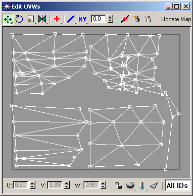
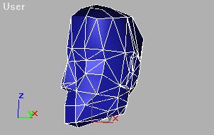
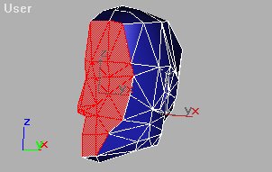
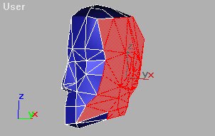
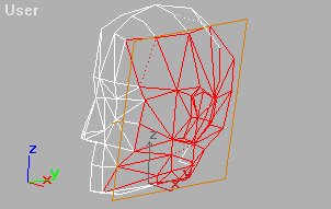
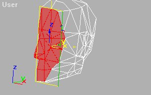
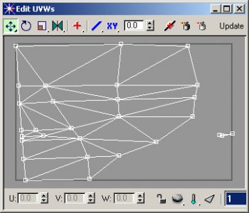
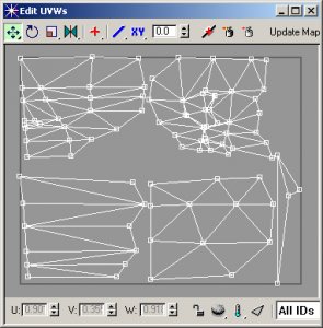
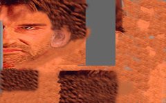
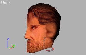
Author: MadTone Skill level: 5 A brief summary of the steps Editable Mesh - Select sets of polygons andassign an ID number to each set. Apply a Mesh Select modifier, use it at Sub-Object level to select Polygons by their ID number. Do not turn Sub-Object off. Apply a UVW Map modifier to the set of Polygons - Planar Map only. Repeat steps 2 and 3 (apply new Mesh Select, do not try to use the previous one). Apply a Mesh Select modifier. Do not turn Sub-Object on. Apply Unwrap UVW modifier. Edit (in UVW Unwrap) select one set of face ID`s at a time and layout the poly`s so that they are separate from each other. Show all ID`s Take a screengrab of the UVW Unwrap Edit window. Paint on the screengrab and save as a .jpg, .tif, or .tga. From the Asset Manager, drag and drop the saved painting to the mesh model. Assigning the Polygon ID numbers Imagine that your mesh was layed out flat, that`s what the UVW Unwrap modifier does. This tutorial will illustrate how to texture the head mesh shown in the following picture : 1. Select the front of the head at Sub-Object Polygon level. Press F2 to shade the selected faces in red. 2. Type in number 1 in the Material ID and press enter. Doing this will assign the number 1 to the selected polygons. 3. Select another set of polygons. 4. Continue selecting polygons and assigning ID numbers. Color Coding the Model Apply a Multi-Sub Object material to the mesh so that you can see if all of the ID numbers are assigned correctly. This material is not used with the final texture, so this is just a temporary material to check where the ID`s are. Make sure that you turn Sub-Object off from the Modify command panel before you do this. Turn Sub-Object off in the Modify command panel. Open the Material Editor. Click the Standard button and choose Multi/Sub-Object from the list. Choose Keep or Discard the original material. It doesn`t matter which, you haven`t changed it. Drag and drop the Sample Sphere on to the mesh. Change the color panels at the right of the Multi/Sub-Object material. You should see parts of the mesh changing color. Look at your model. If any of the colors are in the wrong place, go back to Editable Mesh Sub-Object level and assign those ID`s to the correct numbers. Tip: In Editable Mesh at the Polygon level, click a Polygon and the ID number of that polygon will show up in the Material ID panel. Mapping Mapping a mesh `pins` vertices of the mesh to positions on a picture. This is similar to a dressmaker laying out a pattern onto fabric. In this sequence, you select parts of the mesh and apply mapping to each of the parts. Do the following for each set of ID numbers that you assigned to the model. Turn off Sub-Object for the Editable Mesh. Apply the Mesh Select Modifier. Turn on Sub-Object and choose Polygon level. Click the Select by ID button, polygons with the number that is in the ID panel will become selected. Don`t turn Sub-Object off. Apply a UVW Map modifier. Use Planar, you may need to rotate and re-size the UVW Map Gizmo. Examples: UVW Unwrap Apply a Mesh Select modifier but don`t turn Sub-Object level on. Do this to return the selection level back to Object level. (if you look at the last UVW Map in the white panel it has a star next to the name. The star shows that the modifier has been applied to a sub part of the mesh.& Apply the Unwrap UVW Modifier. Click the Edit button, then open the Face ID drop down list at the bottom of the dialog. Choose just one number to display the faces with that ID number. The name Faces might be confusing, these are actually the Polygon ID numbers that you assigned at the beginning of this tutorial. So what you are doing is displaying only one set of ID numbers at a time. This screenshot of Polygon ID numbers shows a problem with some extra vertices at the right of the picture. These are faces that weren`t assigned the correct number. You will need to find out which number the extra vertices should be assigned to, re-assign them and re-map them. Then, you must re-map Polygons number 1 to fix the map. The above picture is what Polygon ID`s number 1 (on our model) looks like. Scale and Arrange the Sets of faces Screengrab the UVW-Map and Assign the Skin The next step is do a screengrab and to paint on the grab. Make this dialog as big as possible. Make a screengrab of this dialog by pressing the PrtScn button on your keyboard. Alternatively, go to www.techsmith.com and download the evaluation version of Snagit, a really good screen/window dialog capture program. You should be able to see which set of polygons are where on your model. If you can, then you can paint on the polygons. Crop the picture so that the dark gray rectangle is the edge of the painting. Save the picture in your favorite format. Good formats include .jpg, .tif, and .tga. The next step is simple but important. Open the Asset Manager and find the picture that you painted. Click and drag the picture onto the model. The result should show the picture fits perfectly according to the mapping and Polygon ID`s that you set. Finally It is recommended, but not essential that you collapse your object back to an Editable Mesh. It is recommended because most game engines require the UVW Mapping to be built in to the object. Not many game engines will understand the Mesh Select and UVW Mapping if you leave it on an object. The object will retain the mapping that you applied. To collapse the object click Edit Stack in the Modify command panel, then choose the Collapse All option.


-
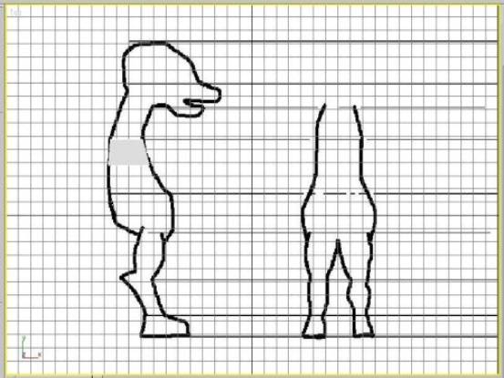
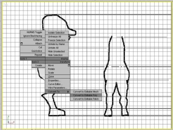
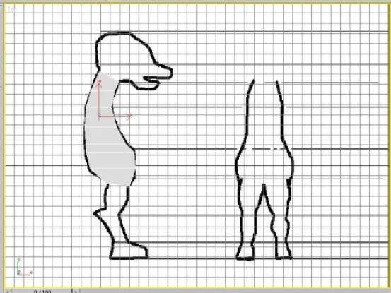
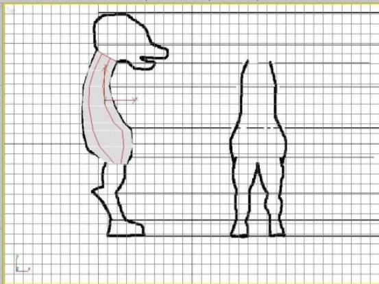
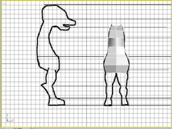
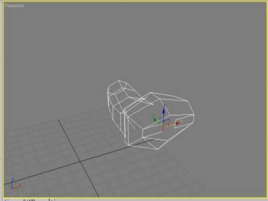
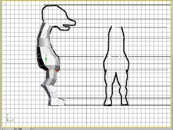
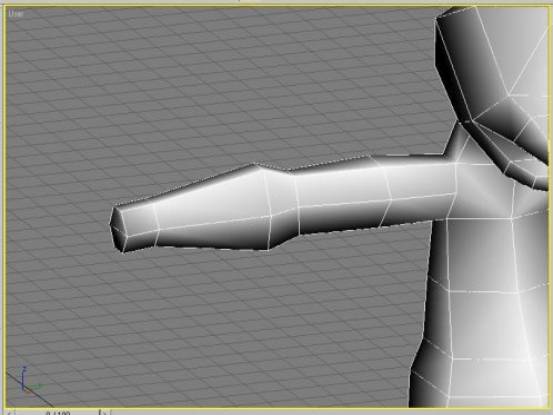
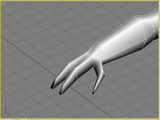
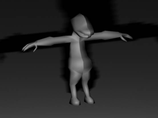
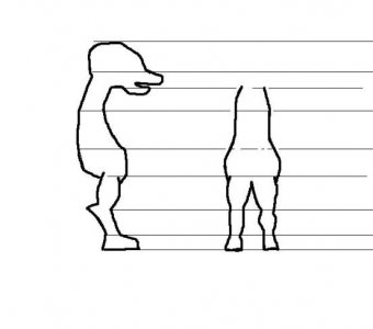
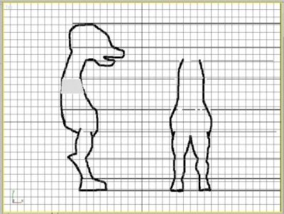
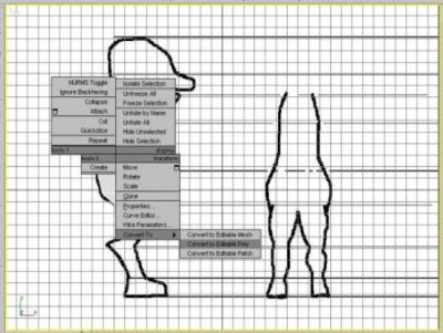
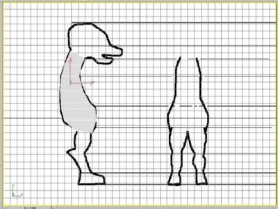
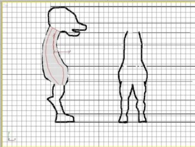
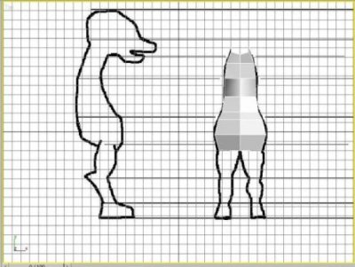
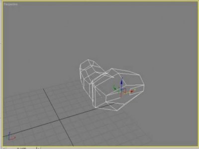
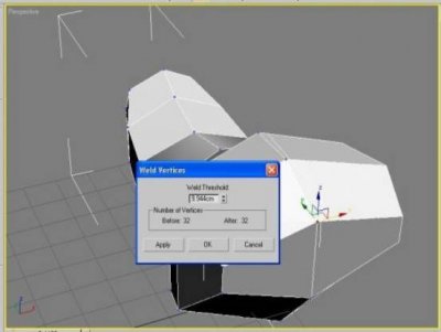
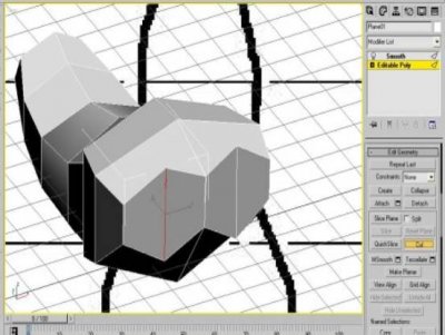
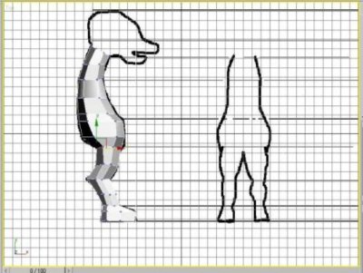
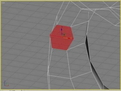
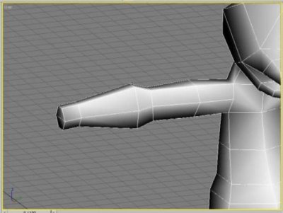
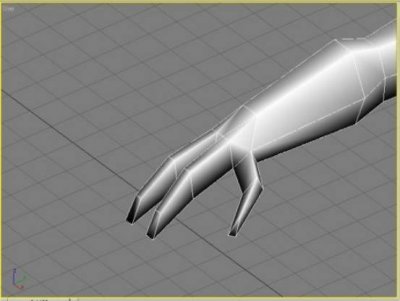
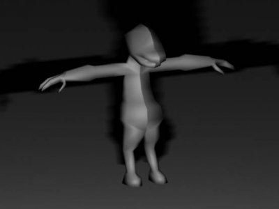
Author: PsycoArmy Skill level: 5 In this tutorial you will find how to build a character model form a simple plane. I will show you how to use Edit poly tool. You will also learn to model using SHIFT + DRAG on EDGE tool to create that shapes you need to start. In this tutorial I will show you how to use CUT tool found in EDGE section, this tool can come in handy in lots of places, also use EXTRUDE to get some of the shapes. This tutorial is done in 3d Studio Max so if you are using something such as GMAX this tutorial should still work fine except for 1 or 2 steps, I will also be showing you how to WELD too, which can be found in VERTEX menu. Here we go. ------------------------- For models you should always try to keep the model in Squares, using triangles is all right with low poly. The purpose of this tutorial is to teach some basic character modelling skills; the methods can also be used in modelling of all sorts of thing not just characters. When modelling a character it is good to use concept even like the one I use here. Create a plane with 1 by 1 sides. Place the plane on the area where you want to start. Right click on your plane and click CONVERT TO > CONVERT TO EDITABLE POLY. Once you have done so u can use VERTEX on the right menu to fit your plane in better. Now we can make the 2D shape of the character. Select EDGE in EDIT POLY menu, click on the first edge you wish to make another segment from, once its selected hold down shift and then move it to the direction you want the segment to go. Continue this until you have the main body part filled like the picture below. Now we are going to use CUT to get the poly amount we need. CUT can be found in EDGE selection down the menu. Using cut is very simple, you just first click cut on the menu, and click the edge where you want to start the new line for the model. Just continue the line through. Now when you have the poly amount you think you need for your model change it to perspective but keep the part selected you want to go out to make the side view. Move it to the side or what ever view your using. Now we can start modelling the 3d shape more. Its good to change it to VERTEX for this one. Move all the VERTEX to make the shape you want it to look like form the front. You can always change position of different VERTEX to make your shapes more to your liking. Always remember that its a 3d environment and you will always need to adjust bits. Now we are going to learn to close off open bits and then model the legs. Use EDGE and SHIFT + DRAG technique here and move it to a good location, use VERTEX too if you need to. Now we are going to weld the VERTEX. Make sure VERTEX is selected, now select the 2 VERTEX you want to WELD. Now WELD can be found in VERTEX, It might be down in the menu a bit in GMAX (not sure). But dont click WELD just yet. Click the little square thing next to the WELD button. This will give you an amount you can WELD to, but seeing you have wot u want to WELD selected just pump it up (you can do this by holding down on the up button and dragging up.) until the 2 VERTEX connect. Remember the WELD button by itself should work fine; just the little square thing gives you more control. Now we will model the legs (in this part I dont keep it squares, I suggest when you do it you keep it all mostly squares, a good 90% of the model should be squares.). Now just cut it form where you want the leg to start, CUT it to how many sides you want it to have. Now just move it to the basic shape it will start as. Now we will use EXTRUDE, first step is to select the POLYGON menu in EDIT POLY. Now select all the shape you want to start the leg from. Now find EXTRUDE and you can use the box next to it for this one, just keep extruding until you have as much poly as you need to make the leg. Now use VERTEX to shape the leg in its front and side views. Perspective is also a good view to use to get the shape right. PLACE PROPER IMAGE HERE (edit it properly ) Im not going to post any pics for this part because its exactly the same for the body and legs. We will be making a shitty headJ; first I just did it as a plane for the basic head shape and just used all the first few steps to get the shapes. Then I used extrude to get the shape for the mouth. I jut used my concept to match it up at the side. I also used weld to attach the head to the body. You can attach the 2 objects by using the EDIT POLY menu where it says ATTACH, just select the first object yo want to attach and then select ATTACH in EDIT POLY and then click what you want to attach it to. ARMS are what we are making now. First make the area you want the arms to start from just like the legs. Now just EXTRUDE and shape it until you have you arm done. Now to make the fingers just use all the past steps, use CUT, EXTRUDE, VERTEX all of the stuff I have mentioned to get the hands you want. It`s good to do one side then clone it and mirror it. Once its mirrored you can weld both sides together, this can get rid of any chance of there being any gap in the centre. I did this model very quickly just for this tutorial, and here was the final I got from it, if you want it you can have itJ. Tutorial Created By Psycoarmy Edited By Genocide
-
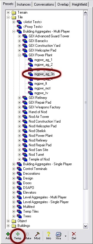
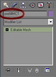
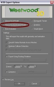
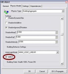
Author: Bumpaneer Skill level: 2 Setting Up MCTs and PCTs Download the MCTs Here or PCTs Here These MCT`s were developed by Bumpaneer with help from Abjab and StoneRook. The PCTs were developed by Bumpaneer with help from AircraftKiller and StoneRook. These soldiers made this project possible. Thanks most certainly goes out to them. Feel free to use these MCTs and PCTs in any map/building you create, but please remeber to include Bumpaneer in the credits. *These instructions only cover setting up MCTs. To set up PCTs follow the same instructions, but DO NOT check the "IsMCT" box* To set up the MCTs for use, first open one of the two files in RenX. Click on a mesh, and go to the Modify tab on the right hand side of the screen (looks like a blue arc). Click on the name for the mesh and replace the default "prefi" with the prefix for your building. You can use no more than five characters for this. Remember most of the Nod buildings start with "mn" while the GDI buildings start with "mg". You have to rename every mesh that starts with "prefi" but DON`T change anything besides that (as far as names). If you want another texture, feel free to use whatever you think looks best. The next step is to export the MCT for use in Level Edit. Goto the File menu, then to Export. On the first screen that pops up, give the MCT a name. A good naming convention is "prefi_mct" where "prefi" is replaced by the prefix for your building. You should save the MCT into the main folder of your mod. On the next screen that pops up, make sure that Hierarchical Animated Model is selected, and then click OK. The MCT should export without any errors or warning messages. Once you have the MCT all exported, open up Level Edit. Choose your mod in the opening screen, and then browse to mgpwr_ag_3n to set up a GDI MCT or mnpwr_ag_3n to set up a Nod MCT. Single click on the file (shown at right) and then click the Temp button at the bottom. A screen like the one below will pop up. On the first screen that you see give the Tile a name. Once again the "prefi_mct" form works well here ("Prefi" is replaced by your prefix). After you have the name typed in, goto the Physics Model tab (second tab). Browse down until you see the checkbox indicated, IsMCT and make sure this box is checked. Then click OK. A Tile with the name you gave it should appear. You can drag this tile under another menu if you so desire, so that it is organized. To get the MCT on the map, click on it`s name and click the Make button. You will then be able to highlight the MCT and drag it to where you want it. I hope these instructions have been helpful, and good luck with all your projects. ~Bumpaneer
-
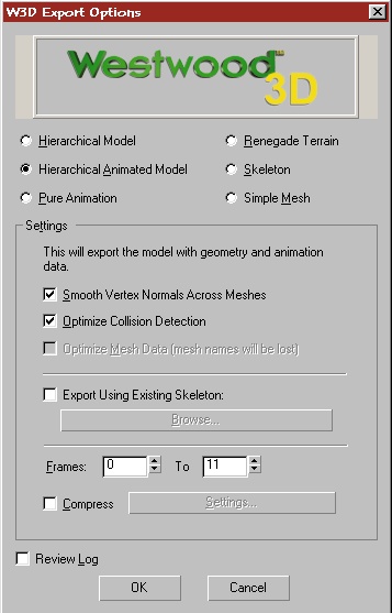
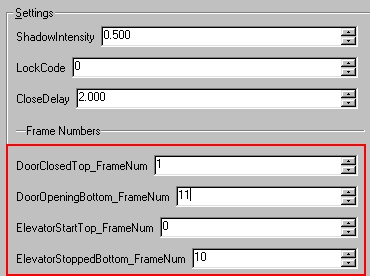
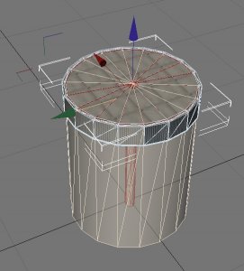
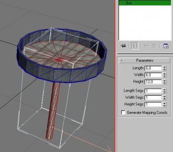
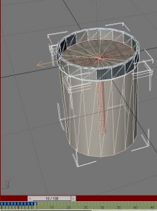
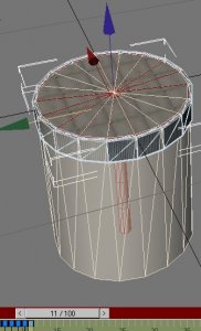
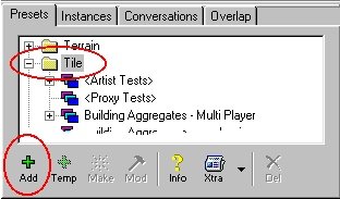
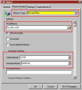
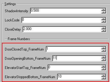
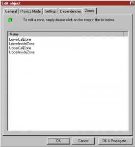
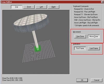
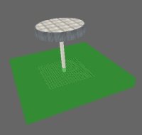
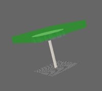
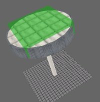
Author: Läubi Skill level: 3 First of all, some things you should keep in mind about elevators: an elevator might cause problems if there are alot elevators, or if people try to use the same elevator at the same time with a slow connection (56k for example) people might fall "through" your elevator and popup at the top after some seconds elevators can NOT transport vehicles! You should always take care that the Transition Zones (explained in the tutorial later) are not reachable for vehicles because the wil get STUCK in them! elevators often cause problems with beacons, if you try to deplay them ON the elevator plattform 1. First Step is of course, create your elevator. This is myone. Ok its not very nice but thats a 2 min one Basicly an elevator has a platform (in this image the red parts), and a door (the blue parts). Of course an elevator can also have other parts in the deep of complexy you want but for this tutorial this is the best choice. Always create your elevator in the center of RenX/Gmax.To get an ide of the size of an elevator, the Single Player ones have an aprocxiamte size of L: 6m, W: 6m, H: 12m You can create a box with these settings to get an idea if your elevator has the right size: (my elevator is a bit too big as you can see, but the size is your choice, you just get a general idea about the size with this method) 2. Because the Rengade-Engine don`t like textured objects that are moving we now create some "cages" that later will be invisible, but responsible for the collision parts. These are basicly just meshes without a texture that covers that elements, that later collide with players. Activate the W3D hide and collision Settings: Vehicle, Camera, Projektile, for the textured Meshes don`t activate any Collision Settings. 3. Now it is time for the animation, an elevator has 3 Animation stages: Stage 1: (Baseframe) Move all your parts of the elevator so it is on the Top-Part, with the door open for enter at the Top: As you can see I just moved the whoe plattform up, and lowered the ring so if the player can enter the elevator at the top. Stage 2: (On the move) Now klick the animate Button, Goto Frame 1 and move your door so it is closed (you can use more than one frame if needed, just note this framae somewhere) Now on the trackbar goto frame 10, and move the elevator down, so it is on the botom with an closed door (same comment as before for the cloe door thing): The best is you note this frame on a paper or something, because you`ll need this later. Stage 3: (Final Animation) Now just make an animation when the door moves down, so you can leave the elevator. My one ends on frame 11, because only one frame is used for open the door in my example, of course you can use as many as you need: Now you`r finihed with this, deactivate the anim Button and feel good that the work is nearly done. 4. Export the elevator to your Modpacket: Export it as HirachyAnimated Model and from Frame 0 to the last frame (in my example frame 11): 5. Open the Commando (Leveleditor), browse to Tiles and press the Add Button Now enter a name, e.g. my_elevator, and switch to the Settings Tab Change the type to ElevatorPhys, Select your W3D and change Collision Mode to STOP, Animation Mode to Manual. Scroll a bit down and set DoorClosedTop to the frame when the door at the top is closed (that is frame 1 in my example), DoorOpeningBottom to the frame where the elevator is at the bottom with open door (Thats frame 11 in my case) ElevatorStartTop that is in nearly all cases frame 0 ElevatorStoppedBottom this is the frame where the elevator is at the bottom with closed door (Frame 10 in my case) Now cahnge the CloseDelay to the Time the elvator should need to go up/down and press OK and your nearly ready for test your elevator. 6. Ok, now its time to tell the elevator where people will wait to enter: Select your elevator again and press Mod, goto the Zones Tab. You see 4 Zones: LowerCallZone: Defines the zone where the Character has to stay in to call the elevator to come to the bottom LowerInsideZone: When you are inside this zone the elvator starts to move Up UpperCallZone: Same as LowerCallZone but for the top UpperInsideZone: Same as LowerInsideZone but for the top When you doubleclick you can adjust the zones t the size / position you need. First / Lastframe switsche between the start and end frame so you easy can adjust the zones. Adjust now all zones like it is explained above. Here are mine: LowerCallZone LowerInsideZone UpperCallZone UpperInsideZone Now press OK and your done with the setup. 7. Load your Level and select your elevator then press Add and it will apear on the map: Export your Map and test the elevator 8. Congratulation! You can now go up and down with your elevator as long as you want.


-
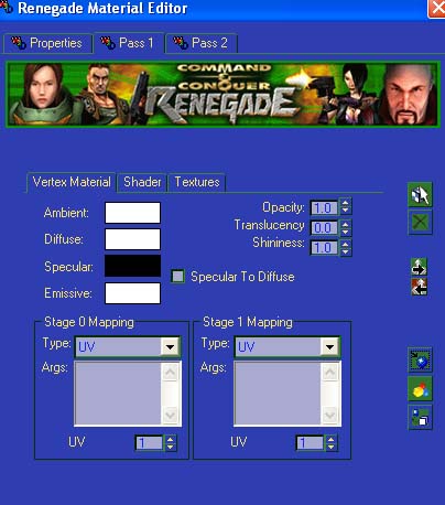
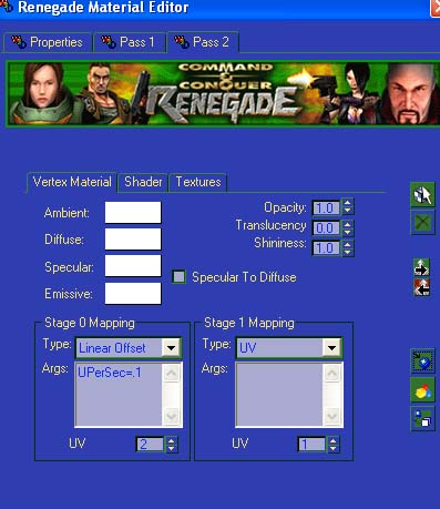
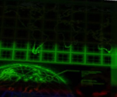
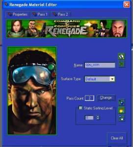
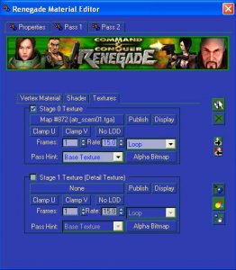
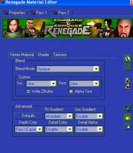
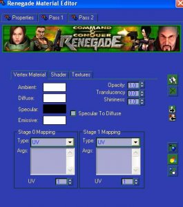
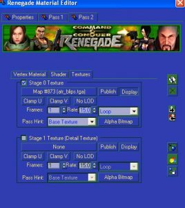
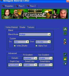
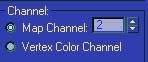
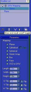
Author: Stonerook Skill level: 3 Project: Duplicate the moving computer screens as seen in MP/SP Renegade buildings computer screens using vertex settings only. Materials: atr_blips.tga atr_scem01.tga hnd_wrksta.w3d (for reference) All found in C&C Renegade's always.dat Programs: RenX W3D Viewer Commando C&C Renegade (LAN Mode Mod Package) This tutorial assumes that you have working knowledge of the programs needed. This means you know how to use them make levels in Commando setup a single player LAN game. Rev. 1.0 02/08/2003 This is the moving computer screen in the Hand of Nod - hnd_wrksta.w3d. Take a look at it the color bars move up and down and right to left. The pattern of the background will take on the colors as the front color texture flows across it. Its a simple mesh plane with two applications of texture (2 pass) and the moving texture is simply a vertex setting. The trick is you have to apply two (2) UVWs to the mesh one per texture. You also need to rotate the second one a certain way to get the moving color bar effect. If you just apply the vertex settings (as per wdump) you will not get the same effect So here is how Westwood did it. Step One In Renx make a mesh 2m,2m segments 1,1 use the front view to make it in. Name it Cpu_test Step Two With the mesh selected Hit the m key. Set your Pass Count to two (2) Name the Material cpu_scrn Select the Pass 1 tab for the next step. Step Three Set this texture to atr_scem01.tga (this is the background texture) Next hit the Shader tab (for Pass 1) Step Four Set your Blend to Opaque as seen above. Next hit the Vertex Material tab (for Pass 1) Step Five Set your VM to the following: (R,G,B) Ambient 255,255,255 Diffuse 255,255,255 Specular 0,0,0 (you could set it to 0,255,0 if you want a glowing neon) Emissive 255,255,255 Opacity 1.0 Translucency 0.0 Shininess 1.0 Your UV is one (1) - for this texture Step Six Select Pass 2 Select atr_blips.tga for this texture. Hit Display on this texture (this is the moving one) Select the Shader tab for the next step. Step Seven Set your Blend Mode to Multiply the rest of the settings should be as shown above. Step Eight Set your all your Vertex Material colors to 255,255,255 down. And your Opacity/Translucency/Shininess are default. Set your Stage 0 Mapping to type Linear Offset Your args will be UPerSec=.1 (caps are important) Set your UV to two (2) Assign the material to the mesh then x out of this dialog. Step Nine Now assign a UVW map modifier and then on the Channel/Map Channel roll down select 2. This allows us just to play with the pass two texture since we put it to UVW 2 under the vertex settings. Now we have to fix the texture to show correctly. Step Ten First flip the map U tile check the Flip box. (this is so the map will display correctly. Second make the UVW map a bit larger than the mesh you can play with the settings to get different settings I made mine 2.5m length and 2.5m width. (different sizes different effects) Then use the use the UVW mapping gizmo and the select and rotate gizmo to spin the UVW map 90° on the Z axis. (Y on the UVW map) So the UVW map should look like this: Now with that done unclick the UVW map option right click on the mesh and change it to a editable mesh this will collapse the mod stack and lock in your settings. (Don't convert it to editable mesh if you want to change the settings on the UVW modifier later.) Now export the mesh as terrain and name it cpu_screen.w3d Open the file with W3D viewer and you should see the a moving computer screen just like the Westwood ones. This is something I whipped up I changed the background texture So by changing the background picture adding some colors from the atr_blips you can make your own custom cpu screens. Photoshop is invaluable in this you can use filters to make the "negative " of your line are to make interesting displays. (I use antimatter) Any questions or comments please email me stonerook1@hotmail.com. Info for this tutorial was taken from the supplied Westwood© meshes and materials. The rest was using the knowledge given by doing the Gmax© tutorials. And the rest a lot of Jolt© soda. If you find this useful please let me know. StoneRook out "patent pending"©


-
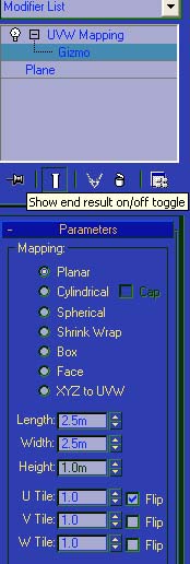
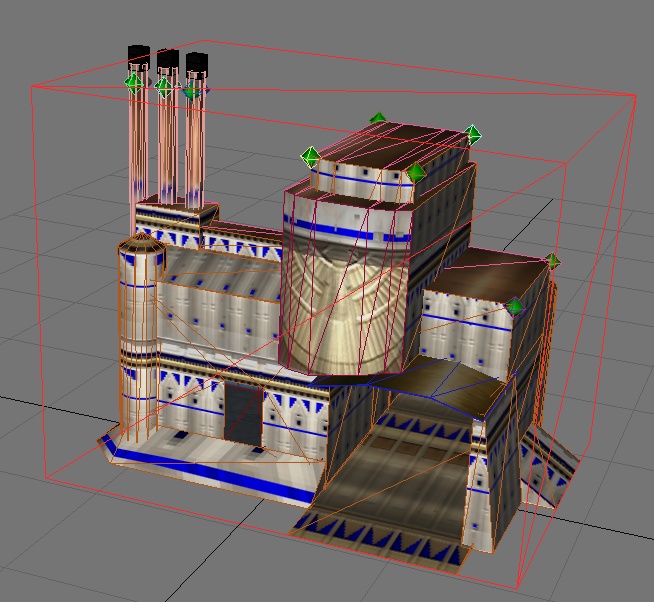
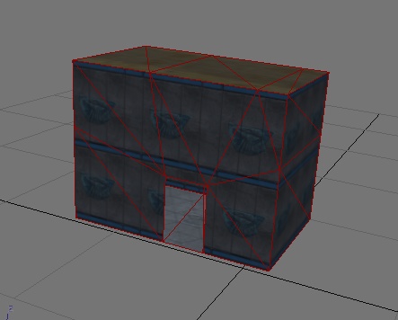
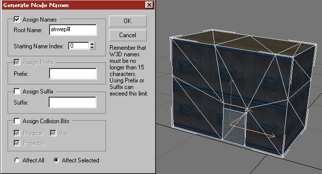
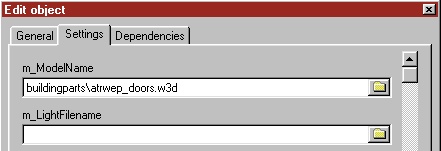
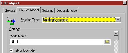
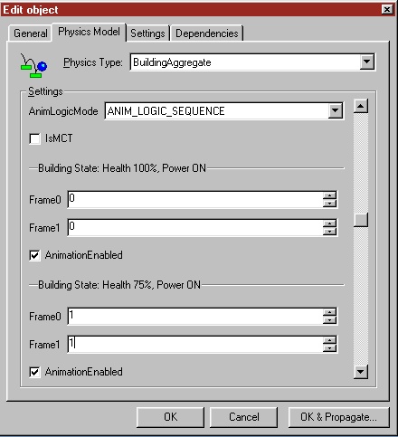
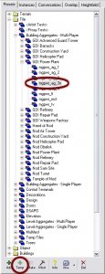
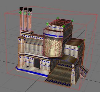
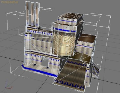
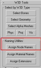
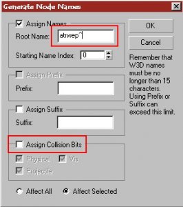
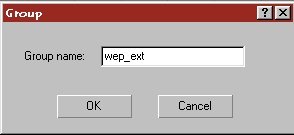
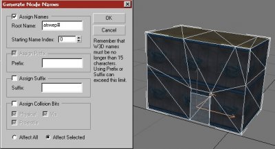
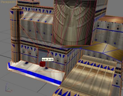
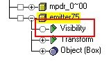
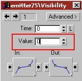
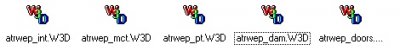
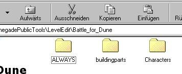
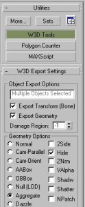
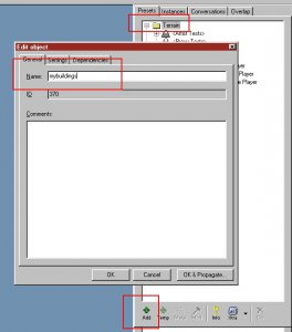
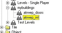
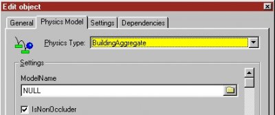
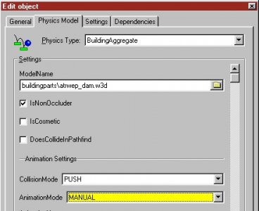
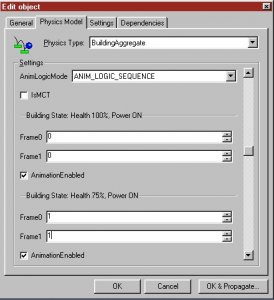
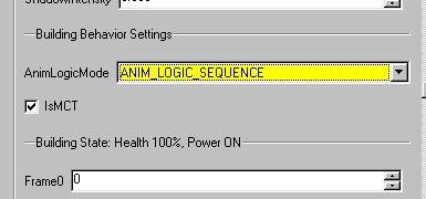
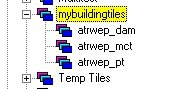
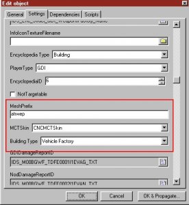
Author: Läubi Skill level: 5 A Step by Step to create a full functional building like the Westwood ones. Important!! Read this tutorial carefully. If something didn`t work as you have expected it, check the coresponding part of the tutorial if you have not miss a thing. 1. First of all, of course you need you building. Mine I use for this tutorial is the Atreides Weaponfactory for the Battle for Dune Mod ( laeubi.de/bfd ) It is important that you move your whole building to the center of RenX. You also should already have setup all collision settings. 2. Now select all the meshes that are part of the EXTERIOR. This should be all parts of the exterior of the bulding, excluding any emitters, animations or doors. Then goto the W3D-Tools --> Assign Node Names: In the following dialog uncheck/check the Options you see on the screen below, enter at the Root Name: entry a short name, e.g. atrwep (atreides weponfactory) followed by a ^. You should write this down. because youll need that later, I`ll refer to this name as the Meshprefix later. The Meshprefix should NOT exceed 6 characters. 3. Congratulation you have now created a buildings exterior. Now goto Group --> Group and enter a name (e.g. wep_ext) 4. Now hide your ExteriorGroup and unhide all parts of the interior, again excluding any emitters, animations or doors. Again select all meshes and open the same dialog as for the interior. Enter the Meshprefix followed by a #. Again Group this and name it for example wep_int: 5. Now we will add the doors, emitters as well as animate them for the later use. If you have already done this, you can just skip this part. For the doors I`ll use the standard Rengade MP ones, but of course you can make your own ones, you find a tutorial at: Door tutorial how to set up those. As you can see, I have unhidden the Ext/Int-Group to better align things. For the doors you need the name of the preset of the door, the standard Rengade doors name is `mpdr_0` create a box 1x1x1 at the topview, and place it at the location where the door should be placed, name the box : mpdr_0~ (or the name your door-preset has in Leveledit + a ~ ) add a 00 after the ~ for the first, a 01 for the second and so on. When you have placed all doors, group the doors e.g. as wep_doors. When you are done with the doors, you need some damage emitters. You can make your own with W3D-Editor or use Renegade ones, extract them with XCC_Mixer you can identify them by the leading e_ (e.g. e_19fire1.w3d). For all Emitters you should extract (or download) the e_master01.tga so you can see the emitter effects: Now create three boxes (1x1x1) named: emitter0, emitter25, emitter50, emitter75. I will refer to this as the `DamageBox`. After that, create 1x1x1 boxes named like the emitter file (without the w3d) that should be displayed later, in this case e_fire1. I will refer to this as `EmitterBox`. IMPORTANT: Never just rename the emitter file!! You must edit the name in w3d-Viewer and re-export it or the file will not be loaded or even crash Renegade!!! Now link the EmitterBox to the DamageBox emitter75 if this emitter should be showed up at the state for when the building is 25% damaged, emitter50 for half damged, emitter25 when the bulding is damaged by 75% and emitter0 when the building is detroyed. For this use the Link tool and klick and drag from your EmitterBox to your DamageBox (The damage box will flash for about 2 sek when this is done succesfull). Then place all around your building emitters or objects that should be displayed at the different states and link them to the coresponding DamageBox. I recommend to save your work now if you have not done this before!! 6. Now we must make an animation, so Renegade later know what parts must be showed at the damage states. For that you should reopen RenX, because the `Trackview` that we will need often conflicts with the RenegadeMaterialEditor for Gmax, restarting RenX solves the problem. Open now the `Trackview`: On the Trackview browse to Objects --> emitter75: Add a visibility track by clicking the eye icon that will add a new option to your Object: Click on the new option and add via the at frame 1, 2 and 3 a new key. Rightklick the first key and change the value to 0 (invisible) Now change this also for key2. The trird key must not be changed and should stay at value 1 (visible) Repeat this process for all other DamageBoxes, but switch the keys to the following: emitter50 frame 1,4,5 emitter25 frame 1,6,7 emitter0 frame 1,8,9 When you have done this, group all DamgeBoxed and the EmitterBoxes e.G wep_emitter 7. Now we will prepare the PT and the MCT (This is optional) Your PT`s and MCT can have also animations like the damage emitters. For the PT`s you might want to add animations for a powerless building like westwood does. for thsi jsut create four more emitter boxes( emitter0p, emitter25p and so on) and count up the last frame by one for each state liek you have seen in Section 6. Select all MCT Meshes and use the naming tool that is described in Section 2, and use as a basename the meshprefix#mct (e.g. atrwep#mct). repeat this for the PT`s also but use meshprefix#pt here (e.g. atrwep#pt) Group all your PT`s and the MCT to a seperate group, e.g. wep_pct and wep_mct 8. Exporting time. Now you must export all parts for the use in Leveledit. Export: * the Interior Group as mesprefix_int (Renegade Terrain) * the Doors Group as meshprefix_doors (Renegade Terrain) * the Damage and Emitter as meshprefix_dam (Hirachy Animated Model) * The MCT Group as meshprefix_mct (Hirachy Animated Model) * The PT Group as meshprefix_pt (Hirachy Animated Model) In my example I`ll get 5 files: atrwep_int.w3d, atrwep_doors.w3d, atrwep_dam.w3d, atrwep_mct.w3d, atrwep_pt.w3d Copy all these files into Your modfolder if you have not done this already, a seperate folder e. g. buildingparts would be a nice idea. 9. Setup your exterior mesh for use in Maps. You might wonder what will happen to the exterior mesh. We must jsut setup some very simple parts to finish this: create a box from the TOPVIEW (1x1x1) in the EXACT center of Gmax/Renx. Name this box meshprefix_int~, then clone the box (or create a new one) and name it meshprefix_doors~ and so on for all w3d`s you have exportet in part 8. then select all these boxes and activate the [x] Hide and [x]Aggregate w3d option. After that select your ExteriorMesh and these Boxes and group them to for example AtreidesWeponfactory and save your work. You can now Merge this Group into your map(s) like the orginal westwood buildings. 10. Setup everything in Leveledit. Now start the Leveleditor and Load your Modpackage. Goto Terrain-->Add and enter a name, e.g. mybuildings Select this new group and press again add. Enter as name meshprefix_doors (e.g. atrwep_doors) and under the settings tab under m_Modelname select your _doors w3d file. Repeat this part also for the mesprefix_int w3d file, you`ll then has 2 new entry`s: Now change to the Tiles Tab and again press add create a new entry named: mybuildingtiles under the Physics Type select BuildingAggregate. Select this new group and once again press add, enter as name: meshprefix_dam, under the Physics Model be sure that the type is Building Aggregate, change the Model Name to your coresponding w3d file, the AnimationMode to Manual Scroll down to the Building Behavior Settings and change the AnimLogicMode to ANIM_LOGIC_SEQUENCE. The Buidling state for 75% to 1, 1 as showed below, for 50% 2,2 for 25% 3,3 for detroyed 4,4. Repeat this also for the State: Power OFF. After that press OK, again use the add, now enter as name: meshprefix_mct (e.g atrwep_mct), select the needed w3d, setup everything like before, but check the checkbox labled [x] IsMCT. If your MCT also has animation sequences, you must set them up coresponding to your animation as described above. Again add another tile, name it meshprefix_pt, set it up as explained for the MCT, but let the [ ] IsMCT uncheked. Now you have three new entrys in your mybuldingstiles group: 11. Congratulation!!! You are finihed now. Add your BuildingGroup you have created in part 9 to your map via the MERGE command in RenX/Gmax, export it as RenegadeTerrain and enjoy your bulding. One Last Step: To make your building work ingame you have to Clone wia the ADD button one of the Buildingcontrollers, for example mine is a Weponsfactory, so I clone the GDI_Weponsfactory: You can name it whatever you want.... but you must fill in the MESHPREFIX into the coresponding field: Of course you can edit other settings like health in this dialog too,play around abit with these settings Have Fun by detroy all your hard work ingame


-
I played it already, it's unique and fun. Would love to try it out in multiplayer.