
CMDBob
-
Posts
70 -
Joined
-
Last visited
-
Days Won
8 -
Donations
35.00 USD
Content Type
Profiles
Forums
Events
Documentation
Bug Tracker
Downloads
Everything posted by CMDBob
-
Step 1: make sure Unreal Engine 4 is downloaded. The project was made in UE4.24.3, but it should work in any future engine version. Step 2: Download the project "here". Once it's done downloading, unzip it to a directory of your choice. Step 3: Open the project. Press "More", then "Browse...", then find where you unzipped it, go into the W3D Texture Baker folder, then open "W3DTextureBaker.uproject". Step 4: Once the project is open, go into the TextureAssets folder, and create a new material (right click in the Content Browser, then select material). Give it an appropriate name, so that you'll remember it. Then, right click in the Content Browser again, and choose "Import Texture Assets". Then, select all the various components for the texture. Ideally, you can just use Albedo, AO, Roughness and Normal for a non metallic texture. For metallic textures, I recommend also importing the Metalness map. Step 5: Set up the material. See UE4 documentation for more details. Step 6: Select the Plane that is in the world, then drag your new material from the Content Browser into the Element 0 box in the Materials section of the inspector. There'll Step 7: Go up one level in the Content Browser, then right click the "Render Texture" object. o to "Asset Actions", and then "Export". Save it where ever. It is in HDR format, so open up Photoshop/GIMP. Step 8PS: Open the HDR image, then set the mode to 8 Bits per Channel. It will open up the HDR toning dialog, I usually use the Equalise Histogram method, but experiment to get the best results. Step 8GIMP: Open the HDR image, then set precision to 8 bits per pixel. Use perceptual gamma (sRGB). Step 9: It's ready now to become a DDS file that W3D can use.
-

Weapon View Model Ammo Counters/C4 Timer Counter
CMDBob posted a document in Weapons, Ammo & Explosions
This tutorial will cover both adding an ammo counter to a weapon (imagine the Halo Assault Rifle's ammo display), as well as adding a timer to the C4 object in the world, instead of having to use an animation to display the timer. It's simple, but does require some setup. Setting up the Number Texture The first step is creating a texture for the counters. It needs to have the numbers laid out in a grid format, like this: 0 1 2 3 4 5 6 7 8 9 - The dash in the grid is for when a weapon is reloading. It could be any graphic, but a dash works well. It doesn't matter if the texture has an alpha channel or not, that more depends on how the texture will be applied to the digit meshes in the model. A sample texture is included in the sample pack at the end of this post. Setting up the W3D Material One important part of the counter system is the material. You will need a W3D Material for this. Set up the material for how you want the texture to look on the weapon, including blending modes, vertex material colours, etc. There is one limitation: You can only use the Stage 0 texture for this (so no detail texture. However, you shouldn't need it.) Once you have the rest of the material set up, it's time to set up the Stage 0 Mapping. Set the Type to Grid and fill in the Args box with this text: FPS=0.0 Log2Width=2 Last=10 Offset=0 Once that is done, the material is ready, and it's time to set up the model part of this. Setting up a weapon view model to have an ammo counter Setting up a weapon to have an ammo counter requires up to 3 meshes to act as the digits (you can have two or even one depending on what you want the weapon to show.) Apply the texture to the mesh, then make sure that the mesh you want the number to appear on is unwrapped so that the UVs only cover the zero on the number texture. Then name the 3 digits appropriately: Name Purpose AmmoCH Displays the hundreds digit (eg 123) AmmoCT Displays the tens digit (eg 123) AmmoCO Displays the ones digit (eg 123) Included in the sample pack at the end of this post is an example weapon view model with the digits set up. Setting up a C4 Timer Setting up a C4 timer is much the same as setting up a view model ammo counter, just that the names that are used are different: Name Purpose TIMERDTM Displays the tens digit of the minutes on the display (eg 12:34) TIMERDOM Displays the ones digit of the minutes on the display (eg 12:34) TIMERDT Displays the tens digit of the seconds on the display (eg 12:34) TIMERDO Displays the ones digit of the seconds on the display (eg 12:34) Included in the sample pack at the end of this post is an example weapon view model with the digits set up. Sample Pack AmmoCounterC4TimerSamplePack.zip This sample pack contains the texture for the counter digits, as well as an example of the weapon ammo counter and C4 timers, in Max 2017 format. The Counter Material is the material that is applied to the digits, to make them work. 19366083.tga -
IntroductionThis guide covers the steps that are required to create a killfont for W3D Engine games. There are a number of steps, and it will require a bit of art skill, as well as some specialised software for this task. This tutorial will not go into setting up the kill messages, as tutorials already exist for this. Required Software 3DS Max. (Can be optional, depending on how you want to create the art for the kill icons). Bitmap art program. This can be Photoshop, paint.net, GIMP or any other program of this sort. I will use Photoshop, but the techniques are the same, and do not rely on anything in Photoshop. Vector art program. This can be Illustrator, Inkscape, or any other vector art program, as long as it can save SVG format files. In this tutorial, I will use Inkscape. FontForge (this application creates the font) Prepare the art for the iconThe first thing you will need to do is create the vector art for the icon. This has a number of steps, and can be done many different ways. I will use the Harkonnen SMG from Battle for Dune as an example for the method I use for this. Step 1: Render a silhouette of the object The first step in this method requires you to render a silhouette of the object in question. The angle of the image can vary, it can be a side view, it can be a forward view, or even a top view. What is required for this stage is a silhouette that is recognizable as the object in question, and for firearms, that view is best gotten from a side view. For my method in 3DS Max, I first create a Standard material, I set the diffuse and ambient colours to pure white, and I set the self-illumination to 100. This will allow me to create a good, clean sillhouette. Fig. 1: Material settings for a silhouette material. Apply this material to the meshes of the gun. If the weapon is already rigged for W3D, hide any bones that may get in the way of the render, such as Muzzle bones or eject bones. Position the gun in the middle of an orthographic view, side on. Make sure the gun fits in the width of the viewport. Fig. 2: Gun model positioned correctly in an orthographic viewport. Once both of these have been done, go to the Render Setup window. This can be accessed via the Rendering menu, or by pressing F10, or by pressing the Render Setup button on the Max Toolbar (). Once that window has opened, change the Output Size to 512 pixels wide and 512 pixels high. Fig. 3: Output size. Once that is done, click render. A window with the side on silhouette should have been rendered. Save that render to a folder with other renders for the killfont. Save it as a 24 bit PNG, and make sure the alpha channel box is ticked. Fig. 4: Settings for saving the weapon render. Once this step is done, you can close 3DS Max at this point, as you are finished with that application. Step 2: Cleaning the Silhouette up Open up the silhouette you just created in the art package of choice. The first thing you want to do is invert the image, making the white silhouette black. Then, you need to clean the artwork up. This stage is more subjective, but essentially, you need to remove, or make more chunky, any small detail in the weapon's silhouette. Small detail will disappear or distort the vector version of the art, so making sure the art is chunky is key. As an example, here is the Harkonnen SMG before and after cleanup. Before: After: Fig. 5: Before and after of the Harkonnen SMG PNGs. Notice how I removed the holes in the gun's front, and made the ironsights chunkier. Things like that go a long way to making a clean kill icon, especially as these will only be as small as the text in game. Make sure you zoom out every now and again to see how it looks small. Once this is done, save the png again and close the image editor. Step 3: VectorizationThis step is the simplest step, and I recommend doing it in Inkscape even if you have Illustrator. Open Inkscape, drag the PNG into the new document, then right click the PNG and hit "Trace Bitmap..." This will open the trace bitmap settings. You shouldn't have to change any settings except for one: Make sure "Remove background" is ticked. You can use the preview window to check what the traced image will look like. Hit OK once you are happy with it. Fig. 6: Trace Bitmap window in Inkscape. Note that "Remove background" is ticked! Next, delete the PNG weapon image. You may have to move the new vector image off of the top of it. At this stage, save the vector version to the same folder as the PNG image, and then close Inkscape. Step 4: Font CreationThis is the trickiest part of the process. Open FontForge. For this example, I will be editing an existing font, Arial MT. Included in this tutorial is a copy of that font in FontForge SFD format as a base. Download it here: ArialMT_BFD.sfd Open that SFD file in FontForge, and it will show you the main font "chart" window: Fig. 7: FontForge main window. When creating a W3D killfont, we need the font "glyphs" (the actual character images in the font) to be in a certain place, the Private Use Area. This area in a font is for whatever the font designer wants to use it for, and is not replacing any existing characters that have a proper meaning in one language or another. To get to that area, go to the View Menu, and hit "Goto". It will pop open a small window. Hit the arrow on the side of the side of the text entry box, and choose "Private Use Area", then hit OK. Fig. 8: The Goto window. This will take you down to a bunch of empty font squares. with names like E000, etc. These are the Private Use Area characters, and they are what we will use for our killicons. Fig. 9: The Private Use Area. E000 is selected, and is the first PUA character in the font. Double click that E000 character box, and it will open the Glyph Editor window. Fig. 10: The Glyph Editor window. At this point, we want to import our SVG icon into the font. Go to File > Import. Change the Format to SVG, and go to where the SVG you created is, and select it. Then, hit Import. Fig. 11: The Import dialog At this point, the icon should be in the glyph editor, but it is a little small. We need the icon to fit inbetween the top and bottom lines, with the "middle" of the gun just a little bit off the middle line (as the middle line is where the "bottom" of a letter without a descender sits.) Fig. 12: Our icon, but too small. Drag a selection box around the icon, then go to Element > Transformations > Transform. Set the transformation to Scale Uniformly, and set the scale to something around 400-425%. Hit apply to see a preview, and if it looks about right, then hit OK. Fig. 13: The Transform dialog, with proper settings. Once that is done, it's time to position it. Drag the icon so it sits roughly in the middle of the top and middle lines in the glyph editor, like this: Fig. 14: Good icon positioning. Finally, drag the rightmost line to just after the end of the icon, so that there's a small gap between it and the gun icon, like so: Fig. 15: Good spacing (the font term for this is kerning, fyi!) This will make sure the spacing between the icon and the text is correct when being used in game. Now close the glyph editor. You should see your new icon in the font. Fig. 16: Our new icon in the font! Save the SFD at this point, we don't want to lose any work. To test the font, we can export it and have Windows install it as a font. Go to File > Generate Fonts..., and then set the type to "TrueType". The font should be generated by default in the same folder as the SFD. Hit OK to generate the font. Fig. 17: Generation Once the font is generated, go to the folder with the font, right click it, and click Install. If you've regenerated the font and are reinstalling the new version, Windows may ask you if you want to overwrite the font. At this point, we can quickly check our new icon in the Windows Character Map program. If all has gone right, the new icon should be towards the bottom of the font: Fig. 18: Our new icon, in the actual font, ready for use. At this point, you can continue making icons to fill up the whole font! Good luck, and have fun!
-
By Greg Hjelstrom with Modifications from the W3DHub team Introduction W3D uses a form of rigid body dynamics to simulate a wide variety of vehicles. All of the geometric characteristics of a vehicle are determined directly from a model which is exported from 3ds-max. For example, the number, placement, and behavior of any wheels in the vehicle is determined by the set of “bones” in the model. Many wheel configurations can be defined by the model: front-wheel drive, four-wheel steering, all-wheel drive, tank tracks, etc can all be set up. Parameters such as the mass, engine strength, and suspension stiffness are set in Mammoth, the W3D level editor. Vehicle Balance/Origin Bone The first thing to do is to position your vehicle model such that its center of mass is at the origin in 3ds Max, this is usually marked by an Origin bone. In the X-Y plane, the CM (center of mass) should usually be placed exactly at the centroid of all of the wheels in the vehicle. If the CM behind this point, the vehicle will lean backwards on its suspension, if it is in front of this point, it will lean forward, etc. In the Z axis, the CM should be placed some distance below the center of the object to help prevent tipping over when turning corners. Collision Detection (WorldBox) As is the case with all objects in W3D, you can use separate meshes for projectile collision detection and physical collision detection. In the case of vehicles you have to use a single OBBox named "WorldBox" for physical collision detection. (Note: physical collision detection is used when the object is moving in the world, projectile collision detection is used when the code is determining whether bullets hit the vehicle). For projectile collision detection, just use some representative meshes from your model. The WorldBox OBBox must be linked to the origin of the vehicle, and be aligned with the world axes. It should also be as small as possible while still containing the wheels and bulk of the body of the vehicle. The physics code in W3D collides with objects in a buffer zone near the surface of the worldbox so it should not completely contain the model. Below is a screenshot of a WorldBox. Note how the WorldBox does not extend all the way to the front, top or back of the vehicle. WorldBox checklist It should be named exactly "WorldBox" (or "WorldBox.00" when part of an LOD model) It should only exist in the top LOD of your vehicle It should be set up to export as an OBBox It should be Hidden It should have its Physical and Camera collision settings enabled It should be the only object in the vehicle model with Physical and Camera collision enabled It should be as small as possible while still containing the wheel contact patches in their initial position (more on this later). Wheels Wheels are defined by adding bones with a particular naming convention into your model. All vehicles, including VTOL aircraft, have wheels. At the bare minimum, there must be two bones per wheel; one to define the contact point of the wheel and one to define the center of rotation of the wheel. The code will use the pivot points of the wheel bones to determine the following things: the initial position of the wheel, the radius of the wheel, the axis that the suspension travels along, and the axis that the wheel rotates about. The two basic bones needed by each wheel are the "WheelP" (wheel position) bone, and the "WheelC" (center) bone. Below is a view of a wheel from the Humm-Vee model (with the WheelP bone selected). Note that the z-axis points along the direction of travel of the suspension and the x-axis points forward. Also, the pivot point of the WheelP bone must be contained inside the world-box. The initial position of all wheels should be at their extreme topmost point; imagine that the vehicle has just fallen off a skyscraper and landed directly on its wheels. Attached to the wheel position bone, you need a bone which defines the center of rotation of the wheel; the WheelC bone. Below is a view of a wheel with both bones set up. Again, the important axis is the z-axis, it points along the axis of rotation of the wheel; in the "Top" viewport in Max, the z-axis should be pointing down your monitor (for all four wheels). The graphical representation of the wheel is then attached to the WheelC bone and will rotate and translate as the vehicle is simulated. The simulation pays no attention to the graphical representation of the wheel or even whether it exists or not. The hierarchical linkage for a simple wheel should look like the one below. Note that the WheelC bone is attached to the WheelP bone; not the other way around. The 'E' at the end of each of the names above is a flag signifies that this particular wheel applies the engine force at its contact point. Through this naming convention you can create four-wheel drive, front-wheel drive, or rear-wheel drive wheels. Other flags that are available include: S - The wheel will turn when the vehicle changes its steering parameter. I - The wheel will turn in the opposite direction of the vehicle's steering parameter (rear wheel steering). T - Intended for tilt steering. Currently a clone of the "S" flag E - The wheel will exert the engine force at its contact point L - The wheel is part of the left track of a tracked vehicle R - The wheel is part of the right track of a tracked vehicle F - The wheel is "fake"; it will graphically move with the vehicle but no forces are computed. H - The wheel is a "Hover" wheel; it will ignore any surface friction and drag, and use the default values. The complete naming convention for a wheel bone is below. The name always starts with the word 'Wheel', followed by a single character and a two digit number (e.g. WheelP00). Following the digits, any of the above flags can be added. Wheel {P,C,T,F} {00} [S] [I] [E] [L] [R] [F] [H] Here are some examples of valid wheel bone names: WheelP00ES - The contact point of wheel 00 which has the engine force and steering applied to it WheelC05 - The rotation axis of wheel 05 which only exerts a suspension force and rolls with the vehicle Advanced Wheel Settings You may notice that there are two more types of wheel bones that have not been described yet. These bones can be used to create wheels whose suspension moves in a manner more complex than simply translating along the z-axis of the WheelP bone. First I'll show an example of a translational constraint using a WheelT bone. This example is from the front wheel of the Nod Recon Bike: The presence of the WheelT bone in a wheel hierarchy causes the wheel to translate along the Z-axis of the WheelT bone rather than the contact point bone. This is used for the front tire of the Nod Recon Bike. The rear wheel of a Recon Bike rotates along an arm. This can be accomplished by using a WheelF bone. Below is a picture of that situation. The WheelF bone will be rotated about its Y-axis to maintain contact between the wheel and the ground (see the picture for how to set it up). This is probably the most complex type of wheel to create... Look at the Nod Recon Bike for reference. Wheel Checklist Each wheel should have a bone named WheelPxx and WheelCxx (where xx is a two digit number) All wheel bones should have all W3D options disabled except for Export Transform The wheels should be positioned at their extreme topmost position (smashed into the vehicle) and their contact points must be contained inside the world box of the vehicle. The hierarchy should look like this: Origin->WheelP->WheelC->Graphical Wheel The Z axis of all WheelP bones should point along the direction of travel of the suspension The X axis of all WheelP bones should point towards the front of the vehicle (direction of rolling) The Z axis of all WheelC bones should point along the axis of rotation of the wheel (typically down in the Top viewport) All wheel bones should have their flags set (append an 'E' to the wheels that are attached to the engine, append an 'S' to the wheels that steer, etc) Turrets Vehicles can have turrets which can fire weapons. The turret aiming motion is generated by the game code as long as certain bones are present in the model. There are three types of bones involved in controlling a turret. The 'Turret' bone will be rotated to set the turret's 'heading'. The 'Barrel' bone will be rotated to set the tilt of the weapon. And the 'Muzzle' bone will be used as the location to create projectiles from. Below is a picture of a the turret from the GDI Mammoth Tank: In the above picture, you can see that there are several muzzle bones. All of the bones follow the convention that their axes should be aligned with the world axes; Z is up, X points towards the front of the vehicle, Y points to the left of the vehicle. If you create your boxes in the 'Top' viewport, they will be oriented in this fashion automatically. One improvement over the linkage shown above would be to attach the V_Barrels mesh as a child of their Muzzle bones because the game engine automatically applies a recoil to the muzzle bone (attaching them in that way would cause the meshes to recoil when the weapon is fired). Vehicles with more than a single Barrel bone If you have a vehicle with two muzzle bones aligned side by-side and offset from the center, you can make the barrels yaw inwards to meet the target. Using the same naming convention that is used for the Muzzle bones (MuzzleA, MuzzleB etc.) you can setup barrels that behave in this way. For example, a vehicle that is setup with a BarrelA0 and a BarrelA1 bone will automatically yaw it's barrels inwards to make hitting targets a lot easier. Below is a picture of how this can be achieved, using a test model. (Image of BarrelA0 and BarrelA1 bones in use) Vehicles with Gatling barrels Vehicles can support barrels that spin, in cooperation with the gatling tech in the weapon definition. To have models with these spinning parts, name the part of the weapon that you wish to spin spin_barrel_x (where x is either 0 or 1, as you can only have two.) and adjust the pivot so that the x-axis points in the direction you want the part to spin (this is normally parallel to the barrel. See the below image for an example. The blue gatling barrels are named spin_barrel_0 and have their pivot with the x axis pointing down the barrels.) Make sure that you still have a Barrel bone, as this does not replace that. Furthermore, make sure that the weapon in use is set up as a gatling weapon! Turret Checklist The model should contain a 'Turret' bone, either a 'Barrel' bone or a BarrelA0 and BarrelA1 bone, as well as one or more muzzle bones. There can be up to 26 Muzzle bone 'sets'. e.g. MuzzleA, MuzzleB, MuzzleC, all the way to MuzzleZ. There can be any number of Muzzle bones per Muzzle bone sets. The number of muzzles per set does not have to be equal. e.g. You could have 2 MuzzleA bones, 4 MuzzleB bones and 1 MuzzleC bone, if you so desire. The bones should be connected in the hierarchy shown above. Visible meshes in the model should attach to the appropriate bones so that they move when the game logic controls the turret (i.e. the turret mesh should be attached to the turret bone so that it will rotate properly) All of the bones should have their pivot points aligned with the world axes. All bones should have Export Transform enabled and Export Geometry disabled. Engine Special Effects VTOL vehicles can control bones to display engine effects. Here are some examples of engine effects: The flame on the Orca engine lengthens when the vehicle accelerates or climbs (EngineFlame) The Orca engine rotates forward and back as the vehicle accelerates or decelerates (EngineAngle) The rotors on helicopters spin when they are in flight (Rotor/RotorA/RotorB) Any bone present in the model which starts with the name "EngineFlame" will translate along its Z-axis along with the vehicle's acceleration. Any bone present which starts with the name "EngineAngle" will rotate about its Z-axis. In the screenshot below, the EngineAngle bone for one of the Orca engines is selected. Below it is the EngineFlame bone and not shown is a skin which has vertices attached to both bones and stretches as the EngineFlame translates. Helicopter vehicles can use the EngineAngle bone to tilt their rotors as they fly forwards and backwards. In addition, they can contain 'Rotor' bones which will spin about their Z-axis when in flight. The parameters for how much these bones rotate and translate are all controlled through settings in the level editor. Engine Effects Checklist "EngineAngle" bones will rotate about their Z axis "EngineFlame" bones will translate along their Z axis "Rotor" bones will constantly spin about their Z axis while the object is in flight "RotorA" bones, which are hidden when the rotor angular velocity is above or equal to the RotorBlurThreshold "RotorB" bones, which start hidden and are unhidden when the angular velocity is above or equal to the RotorBlurThreshold Aircraft Specific Effects Aircraft have some extra bones that the game can control to give the appearance of proper flight controls. The engine can simulate the Ailerons, Elevators and Rudders of a plane. The ailerons control roll, elevators control pitch up and down and the rudder controls yaw left and right. This image shows a full set of flight control surfaces in 3ds Max (Ailerons in green, rudders in red, elevator in blue). Ailerons rotate around the Y-axis, elevators also rotate around the Y-axis and the rudders rotate around the Z-axis. You can have up to six ailerons, six elevators and six rudders per vehicle. Vehicle Damage As a vehicle becomes damaged, the game code can un-hide particular bones in your model. This can be used to show damage by attaching emitters to those bones since emitters in the model will start emitting when the bone they are attached to becomes un-hidden. There is support for three stages of damage, activated when the model reaches 25%, 50%, and 75% damage. When the model loses 25% of its health, all bones whose names begin with DAMAGE25 will be un-hidden. Once the object has lost 50% of its health, all bones whose names begin with DAMAGE50 will also become un-hidden. And when it has lost 75%, the DAMAGE75 bones will un-hide. Inverse Kinematics Vehicles can have a simple inverse kinematic system, with a maximum of 4 pairs of bones. This can be used for hydraulic systems on vehicle turrets, recoil hydraulic absorbers, etc. The system will rotate the two bones along their Y-axis so that they will always point at each other along their X-Axis. To set this up, have two bones, with the same root name and either IK0 or IK1 at the end. For example, in the below image, the two selected bones are named hyd_ik0 and hyd_ik1. They face each other along the X-Axis (the red arrow) and they rotate along the Y-axis (which points out of the screen in this side on view). These bones can't be parented to each other, but they can be parented to objects in the scene. For example, in the image, the top IK bone is parented to a barrel bone and the bottom IK bone is parented to the chassis, This will allow the hydraulics in the model slide in and out properly as the barrel pitches up and down. Physics Parameters All of the actual physics parameters are controlled through the Mammoth level editor. When creating a vehicle, the first thing you have to do is choose the physics model that it will use. There are five main physics models for vehicles: WheeledVehicle, TrackedVehicle, Motorcycle, VTOLVehicle and AircraftPhys. Parameters common to all vehicles Mass - the mass of the vehicle GravScale - a scale factor that is applied to the gravitational force on the vehicle. This is set to 2.25 for most vehicles. Elasticity - not currently used. AerodynamicDragCoefficient - controls the amount of drag. Spring Constant - spring constant for the suspension (even VTOL vehicles have a suspension) Damping Constant - damping in the suspension springs Spring Length - suspension length, wheels start at their initial position and can translate down this far Traction Multiplier - scales the amount of traction available to the vehicle Lateral Moment Arm - length of the rotational moment arm for lateral forces at the tire contact patches. this lets us fake the lean of the vehicle when turning without having to adjust the W3D model. TractiveMoment Arm - length of the rotational moment arm for tractive forces at the tire contact patches. This lets us control how much the vehicle "dives" when it brakes and how much it leans back when accelerating. EngineFlameLength - if the vehicle has an "EngineFlame" bone, this controls how far that bone will translate. Since this parameter is available to all vehicles (not just the Orca), we could create things like Recon Bikes and cars that have a flame emitting out of their engine. Parameters specific to ground vehicles MaxEngineTorque - this is the torque that the engine can output. For tracked vehicles we don't have a sophisticated engine simulation; this torque is simply divided between the wheels and applied (also scaled by user input) EngineTorqueCurveFilename - this is the engine torque curve (relates torque to engine RPM). These curves are created with the "SimpleGraph" tool Gear Count - number of gears in the transimission GearRatio[0-6] - transmission gear ratios FinalDriveGearRaio - gear ratio in the differential DriveTrainInertia - inertia in the drive train components ShiftUpRpms - point at which the code shifts into a higher gear ShiftDownRpms - point at which the code shifts down to a lower gear MaxSteeringAngle - maximum angle of the steering tires LeanK0 - internal torsional spring constant for motorcycle "balancing" LeanK1 - internal torsional damping constant for motorcycle "balancing" Parameters specific to VTOL (Vertical Take-Off and Landing) vehicles MaxHorizontalAcceleration - acceleration of the vehicle in the X-Y plane MaxVerticalAcceleration - acceleration of the vehicle along the Z axis MaxFuselagePitch - angle that the vehicle pitches when acclerating forward MaxFuselageRoll - angle that the vehicle rolls when strafing or turning PitchControllerGain - spring constant for the pitch controller PitchControllerDamping - damping constant for the pitch controller RollControllerGain - spring constant for the roll controller RollControllerDamping - damping constant for the roll controller MaxYawVelocity - how fast the vehicle can spin YawControllerGain - how fast the vehicle reaches its MaxYawVelocity RotorSpeed - how fast the 'ROTOR' bones should spin RotorAcceleration - acceleration of the 'ROTOR' bones RotorDeceleration - deceleration of the 'ROTOR' bones RotorBlurThreshold - determines the angular velocity at which RotorA/B bones are swapped. Parameters specific to Aircraft Parameter Default Short Description MaxEngineThrust 0.0 Maximum thrust produced by the engine MaxReverseThrust 0.0 Maximum reverse thrust, used for reversing on the runway (not realistic, but necessary) ThrustGain 0.0 Sets the throttle response speed, i.e how quickly we can throttle from 0 to 100% and back MaxCruisingSpeed 0.0 Sets an upper limit on the maximum speed of the aircraft ElevatorGain 0.0 Sets the rotation intensity for pitch ElevatorDamping 0.0 Sets rotation damping for pitch, limits maximum pitching speed AileronGain 0.0 Sets the rotation intensity for roll AileronDamping 0.0 Sets the rotation damping for roll, limits maximum rolling speed RudderGain 0.0 Sets the rotation intensity for yaw RudderDamping 0.0 Sets the rotation damping for yaw, limits maximum yaw speed LiftCoeff 0.0 Lift coefficient, higher value means aircraft can achieve the same lift at a lower speed (i.e stay in the air while moving slower) BrakingAction 0.0 Sets the strength of the brakes, helps stop faster on the runway LandingGearMaxSpeed 0.0 Sets the maximum speed at which the aircraft can move when the landing gear is deployed DihedralWings false If set to "true", aircraft's wings are assumed to be dihedral, which means they automatically try to level out the plane if its wings are not parallel with the ground RStabilization 0.0 Sets the intensity of roll stabilization (see: DihedralWings) MaxSteeringAngle 30.0 Sets the maximum angle that the aircraft's flaps can be rotated to (should be kept between 0 and 45 degrees) MaxEngineRotation 25.0 Sets maximum engine rotation (for visual effects only) RotorSpeed 360.0 Sets maximum rotor speed (for visual effects only) RotorAcceleration 180.0 Sets rotor acceleration (for visual effects only) RotorDeceleration 180.0 Sets rotor deceleration (for visual effects only)
-
That's actually a good question! At the moment, they're AI controlled, I'd rather not have players have to constantly man defences if I can help it, as it's not the most fun thing in the world. However, I am considering some defences that are unmanned that a player can jump into as well. Those would be smaller affairs, more a gun on a mounting than a full position like these. Having a few positions where the defences can be bolstered if needs be is a fun idea. (They could even be purchasable and deployable/undeployable... Plenty of ideas for things that could be done, but ATM I'm trying to keep it simple with an anti-infantry, an anti-vehicle and an anti-air defence for each side.) As an addendum, I've got ideas for larger defences, for larger, higher tech bases (stuff like artillery guns, full sized SAM defences, CIWS type things...)
-
If you mean the pistol grips, it's an attempt to replicate the checkering on the bakelite grips. It's very tricky when you've got 9 by 6 pixels out of a texture that's 16 by 16 pixels! 😋
-
@CMDBob here, and I think it's time for a proper announcement for my W3D game; Cold War Confrontation. The Situation The year is 1987… more or less. The forces of the North Atlantic Treaty Organization (NATO) and the Warsaw Pact (WARPAC) are facing off. Escalating tensions between the two factions have led to a situation where one small spark will be enough to set off a war. Then, out of the blue, both sides come under attack. NATO forces begin tactical airstrikes, and WARPAC tanks begin pouring over the border. The cold war has gone hot. However, forces beyond both factions are moving, deep underground… At this point, neither side knows, though. Even if they did, neither side cares. Each believes the other struck first, and it’s now a fight to the finish, be it the Red Army at the Rhine, or NATO at the Russian border. Will this end in stalemate, a victory for one of the armies, or nuclear fire? That remains to be seen. The Game Cold War Confrontation is a W3D based FPS game, involving combined arms warfare, with a unique visual style for the engine. Use a large number of weapons and vehicles across a variety of terrains, from urban city centres, luscious islands, and cold winter mountainsides to destroy the enemy team. Not every mission is a search and destroy, however, as sometimes, your objectives will be things beyond simple destruction, and may require more strategy. At this early stage, the 2 main factions are the US Armed Forces and the Russian WARPAC forces. The initial release will be infantry and light airdropped vehicles, as to give people a taste of the full warfare that is coming. The plan for the future is a full US/Russia release with full land/helicopter combat/bases, then releases with more NATO/WARPAC factions (such as the British Armed Forces, Czechoslovak People's Army, Bundeswehr, Nationale Volksarmee and more), as well as fixed-wing air forces and naval at some point. Know Your Equipment - Issue 1 I'll be presenting some of the weapons, vehicles, buildings, etc, that make up Cold War Confrontation. For this announcement, here's the basic weapons of the NATO forces and the Warsaw Pact infantry. The Beretta M9 and MP-443 Grach pistols are the primary sidearms of all soldiers. Every soldier has one (except for a few certain classes, which get something with a little bit more of a bang...), and these have infinite ammo. They aren't the most effective weapons, but it's better than nothing. The M16A3 and the AK-74 are the basic rifles for the basic infantry class within Cold War Confrontation. Reliable, dependable and sturdy, these weapons are good starting weapons. They also have numerous variants within the game, which I will expand upon in later updates. Keep your eyes peeled for updates within the W3D weekly updates. A final word from @CMDBob So, finally an announcement. I’ve been working on this for quite a while (the first Git commit to the project repo is on the 15th of December 2018, but I’d been working on it a while before that point. Plus, a lot of the vehicle models date back to as far as 2014). Glad I’m finally formally announcing the project. I’m having a lot of fun making it, and I hope that people eventually have fun playing it! As for my plans: I hope that I can get a build of the game out to testers as soon as possible. The main thing that I need to do is content at this point, as I’m essentially building everything from scratch. However, the more content I make, the more stuff I can use in other maps, so it’s not all bad. 😊 I’m not sure on the public release timeframe, as I want a fair few more maps before any sort of release. Still, I’ll try and release some news as often as I can. Might only be a short update on a weapon, vehicle, building, or even a game mechanic, but it’ll be something to keep people's attention!

-
 Just a quick FYI, if the plugin's giving you errors in Max on loading (error code 126) you'll need to install the 64 bit VS redistributables, located here: https://aka.ms/vs/16/release/vc_redist.x64.exe
 -
Yeah, I can do green!
-
Here's some quick screenshots I've taken of RA_Bunkers and RA_TheWoodsToday. Oh, and here's a quick couple of shots from Shallow Grave, showing the gem island in the middle (that's missing from the original RA map), for reference. My own thoughts? I do quite like Shallow Grave, but I do also love The Woods Today, and with some nice work could be something really nice.
-
The roadmap is looking really good, and I can't wait to see some of the new stuff in action. I'm really glad that there's tools being worked on to replace the ancient LevelEdit and Max 8 W3D exporter, should make modding W3D a whole lot easier with the more modern toolchains (especially 3ds max, it's such a pain building stuff in a newer version of Max and having to backport it to 8... not fun.)
-
Just a small gap in the terrain, near the Allied hillside turret on RA_Zama. See image here: https://imgur.com/jwpxIE4
-
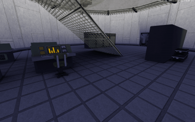
Sorry I've not posted anything, I needed a bit of a break (plus work takes up a lot of the day, really...). At any rate, I've been working on the shadow issues with all the props, and I've worked out a nice, neat little solution. I light mapped it. (The first shot is a little older, before I created a proper 3ds max transparent material for the railings. Now, it's not perfect, by any means (and I still need to relightmap the shelving, as that's why there's a really strong shadow, the ambient occlusion was a bit too high, it seems. It's tweakable though.), but it's way better than it was before, AND it'll take less polygons. I still want to get some sounds added, and the chairs won't be perfect, as they aren't lightmapped (but I have, in an effort to try and help fix the shadows on them, subdivided the seat and the backrest part. I might go back and redo that a little bit.) The room lighting might still be a bit off, but it's a tradeoff, make the lights any smaller and they won't cast light properly, any larger and they'll swamp the room out. (besides, it doesn't look that much worse than the existing APB building lighting...)
-
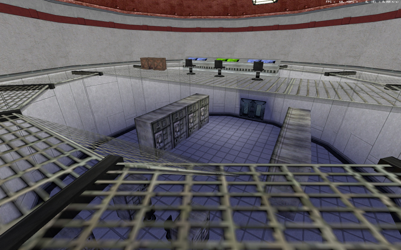
Since I've last shown stuff off, I've done a lot of work. Took Raap's advice in the mainframe room, and made the new supercomputer fit in better. I also took some advice from Pushwall, and added 2 new exterior doors to the building. Plus, added a small little storage closet as well, makes it feel a bit bigger inside. Then, I also went and made some new props, including some new shelving for the new storage room: As well as a new console to replace the ugly one I ripped right from Renegade: And a smaller miniconsole to replace the old Missile Silo computer box thing: (oh, and some new chairs to replace the roughly 20 poly chairs that were there before, you can see them in the pictures above.)
-
I was going to change that texture, I noticed it looked like crap, and while it was the original texture, it's outlived it's original purpose. I've redone it with a much, MUCH nicer, higher res texture. I was also going to slap some trim down and make the edge look nicer and carved in, but forgot. EDIT: New trim. Much better.
-
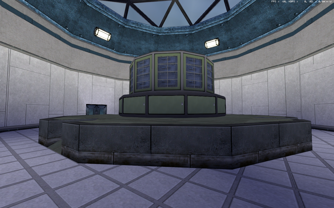
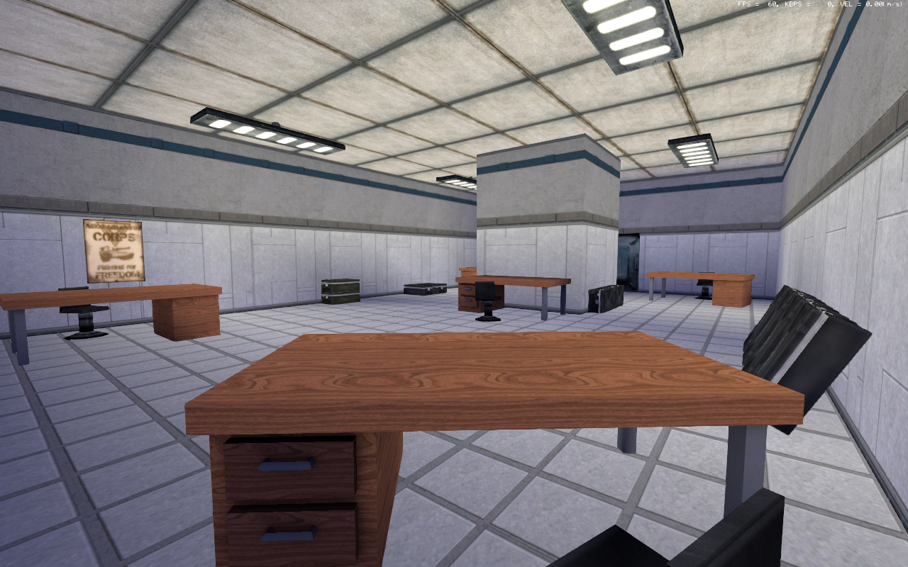
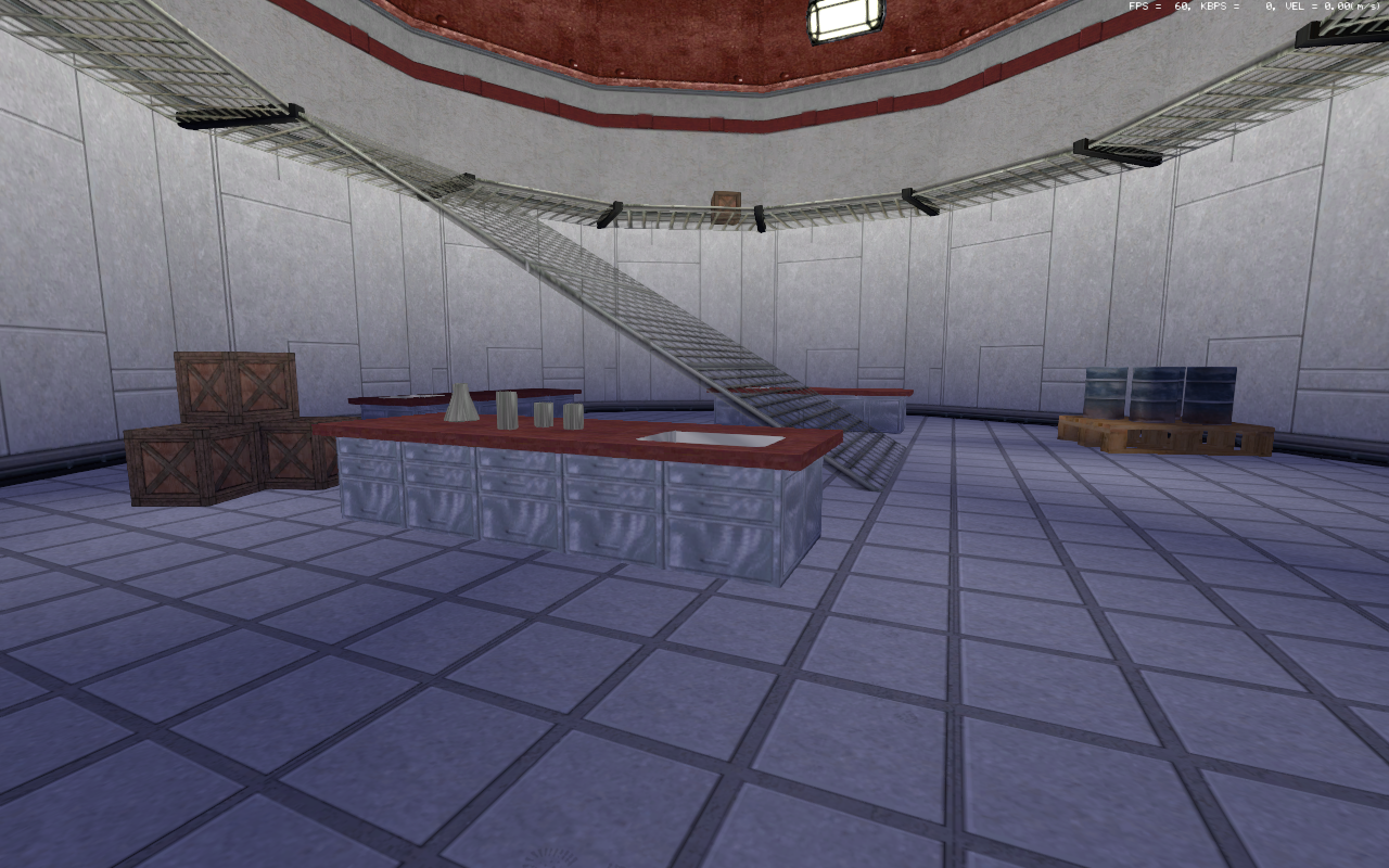
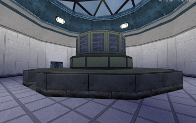
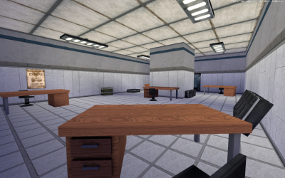
Right, couple of things: Got the computer centre version of the building pretty much done. I still want to make the oscilliscope version of the tower computer, make a new chair for everything and retexture the sit down desk console that I have at the moment, but otherwise, it's pretty much done. The big dome now has this inside it: A large supercomputer unit, in the middle of the room. The "atrium" room with the ladder to the roof now has a tonne of desks in: Many people on the Discord have said that it looks like it's out of the Facility in Goldeneye. I'd... have to agree with them. (Plus, I wish APB had more posters and stuff in it, it's kinda hard to decorate rooms like this without them... Ah well.) Oh, and one last thing, I did a new version of the Iron Curtain effect on the testbed. It's now a simple two pass material, one with the base vehicle, and then the existing Iron Curtain effect I whipped up alpha blended on top of the vehicle, so you can more easily identify the thing, but it still glows with ominous, red, invulnerable, communistical energies.
-
I've worked something out for the Iron Curtain effect and it's test vehicle: (it's just a Tesla tank without the Tesla dome. Perfect for filling full of scientific equipment for monitoring the Iron Curtain effect.)
-
That's a good idea, and I'll probably end up doing that. It'll be a slight squeeze, but nothing too bad. Blinkenlights! As I said on the discord, it's just one mesh for all the 32 lights, with a detail texture set to Scale and using the Step UV mapping, to go through a sheet with the brightnesses for the lamps. 8 different patterns, so 4 lights per pattern. They look quite good actually in game, too!
-
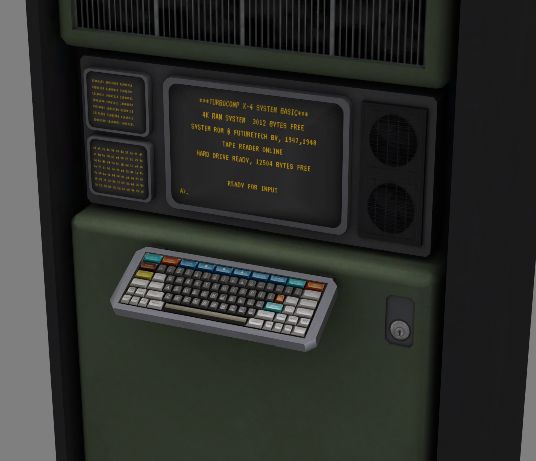
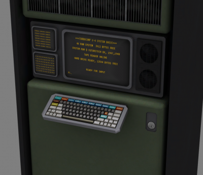
Well, got the C unit made for the data center. Was quite fun to make, as well. Got some nice scanlines on the screens, as well as a lovely reflective effect. Just got the two other units I want to do (the blinkenlights unit, and a round, radar/oscilliscope screened unit) and then a few other ancillary props, like desks and that. Then layout of the computer center version, then onto the chemlab version with lots of barrels, vats of goo and workbenches. Then, I want to make an Iron Curtain research center version, which will combine elements from both the computer and chemlab centers, as well as a mini-iron-curtain in the largest dome.
-
Yeah, it's handy to have inspiration. I've taken a little bit of inspiration from Team Fortress 2, as it's computers full of blinkenlights and such are very useful for ideas. I've got 4 of the big mainframe towers planned, the A unit which is just the plain box, a B unit which has a reel to reel drive on it, a C unit which will have some screens, and a keyboard attached, and a D unit which will be lots of blinking lights and such. (I plan to have some fun with the blinking lights and make them flash in patterns and that, using UV scrolling and detail textures for the brightness of the lights...) I might go and make some half height units too, and a console and that, in the same style. (Then, some simple desks as well, for the "atrium" type room.)
-
(quick note, I wrote the majority of this a couple of days ago, but forgot to post. ah well.) Yeah, I'm more mashing them together as this "layout" is just to get some of the rooms all laid out and some of the props (such as the chemistry workbench) tested. (Testing did reveal some major alpha sorting issues with the glassware on the chemistry workbench, as they were fully transparent. Got rid of the alpha transparency, unfortunately. Ah well...) I'll probably do 3-4 variants of the interior (data vault, chemical lab, iron curtain lab and prison). For now, just want to get a few more props made up (such as a desk) and that. ---------------- Since I wrote this, I've been working on a new set of "mainframe" props, similar to the untextured wip props shown above. I've got a quick W3DView screenshot of one of them. It's not as detailed as the above props, but it'll do for my purposes. Looks a bit better than the existing one, at any rate!
-
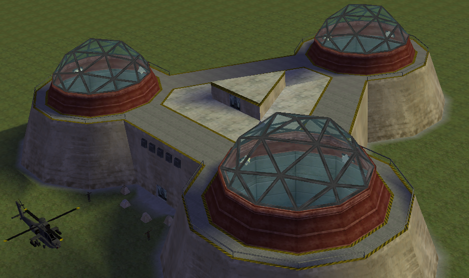
I've been taking the advice into account, and I've done some renovation to two of the domes, one into a computer center and the other into a bit of a chemistry lab. I've changed a good amount of the textures, to make it feel more like a clean, clinical lab. Still debating what to do with the last dome. I was thinking some sort of sciency radar... gizmo, maybe iron-curtainy, or a prison block area. Could potentially do both, for different purposes. The building looks more sciency at any rate. (It's hard to fill buildings with stuff, especially if you have to make it all.)

-
Yeah, I did think some of the textures were too tiled. I'll probably end up re-texturing and using different, less obviously tiled textures, as well as bumping up the vertex count for the large, flat polygons. I've made a couple of "new" textures that match the colours of the building from the render, and I've remodelled the domes, so they're actual polygon domes. The main issue is props, as there's not that many "sciencey" props in APB. Hell, there's not that many props as is. I'll see what I can do, though. Put a quick snap of the "renovated" exterior with the new domes. (I still need to subdivide the mesh for better lighting...)

-
Thanks. I might have a go at upgrading the hospital, too, as that's in the 9935 files. The hospital actually seems harder, really, as it's in a much later stage of development, and there's textures that are totally missing and I'll have to work out replacements for. (also, I think the hospital is bigger than this!) Yeah, a Soviet Seamist with this being the objective could be rather fun. There's some interesting things in the old 9935 building pack, really, like a few alternate layouts for building interiors like the War Factory, which has 3 different interiors in the pack (the one we know and love, minus the stairs which came later, and 2 variants, which both have underground sections, but they're both very different), as well as an alternate refinery interior that had stairs (and a really awkward set of stairs to the downstairs "tunnel" area), plus a few other bits and bats (like the old ice covered warehouse from Fjord, as well as the aforementioned Tech Center and Hospital.) EDIT: Made a big whoopsie, had the old 9935 bunkerwall texture in my APB dir. New shot of the exterior with the proper texture: (I'd have edited the first post, but there's like an hour timer on it. oops.)
-
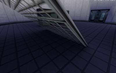
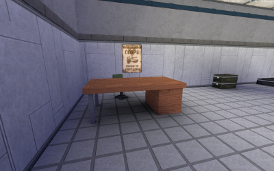
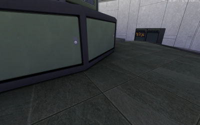
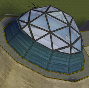
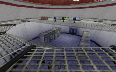
So, I was poking round the really old APB 9935 gmax building source files, and I noticed there was a civilian technology centre model that was half finished. So, I decided to finish it. The exterior of the center. The entrance to the facility. Simple, but it works. One of the research domes, with a couple of computer(?) stations. The largest dome, still under construction. The last dome, with just a few crates and a catwalk. The central atrium, with stacks of crates, and the roof access ladder. Going up... The roof. Be careful not to fall off! Finally, a view from the top, complete with a look into the domes! I've attached the 3ds max source files (the building itself, plus a proxy and edge for cutting into the ground), as well as the two textures that are missing from APB. (Just the metal floor on the roof and the actual dome texture.) They're all in one archive. civtechnologycentre.7z In terms of what this could be used for, I'm not sure. It's big, sure, but not too massive. (It's a little bigger than 2 x 2 war factories, but the inside is a fair bit smaller than that.) It could make the centrepiece of a TDM map (with extra ramps to the roof added, and maybe one of the domes removed and a ramp up there...) or an objective in a mission map (defend/assault the tech center? Capture the tech center and hold it for 5-10 minutes to win? The possibilities are endless...) or, it could just be a big prop. (Capture it to unlock the ability to produce a special trooper/tank?) Anyway, it's there for people to use.